
Load-Bearing Wall Identification: Joists, Basement Supports and Roof Loads
Trace joist bearing, basement supports, roof reactions and lateral bracing before planning a wall opening, with the checks needed for temporary support.
Joist direction is a clue; actual bearing is the deciding question
A wall running across floor joists may support them, but it can also be a partition beneath joists that span past it. A wall parallel to the joists may conceal a post, support a beam or contribute to lateral resistance. Start with the framing arrangement above and below the wall, then have a qualified structural professional establish its function before anyone cuts it.
The useful question is where the load goes. Roof and floor loads travel through members and connections into supports, foundations and soil. Following that route explains why a wall matters more reliably than its position in the room, the sound of tapping drywall or the thickness of a finish. It also reveals whether a proposed replacement beam would create new concentrated loads below.
This guide helps organize a preconstruction investigation. Use it with the structural framing and foundations guide and the LVL table guide. The latter explains manufacturer table conditions; the designer still needs the building’s actual framing, loading and support details to select an alteration.
Begin with drawings and an accessible survey
Collect the original structural plans, later addition drawings, available permits and roof-truss design sheets. Compare them with the building rather than assuming every alteration was recorded. A later opening, replaced stair, added bathroom or remodeled attic can change the load path without changing the room’s overall appearance.
Draw the proposed wall opening on a simple plan. Mark the floors above and below, approximate joist direction where safely visible, nearby beams, columns, roof changes and utilities. Label what is visible and what needs investigation. Photographs are most useful when their location and viewing direction can be tied to that plan.
Begin in accessible unfinished spaces. A basement, crawlspace or attic may expose framing, but safe access and footing come first. Do not crawl onto unsupported ceiling finishes or move structural braces to improve visibility. If an area is inaccessible, arrange professional inspection rather than treating the absence of visible evidence as proof that no support exists.
Read the floor framing above the wall
Look for joists that terminate, lap or connect to a beam at the wall line. Those details can establish a bearing location when interpreted with the rest of the structure. Follow each member far enough to identify both supports; a short glimpse through an opening may hide a hanger, cantilever, splice or change in framing direction.
A perpendicular wall deserves investigation because many floor systems bear that way. However, joists can cross over a non-bearing partition without relying on it. A finish touching the joists does not establish that the wall was designed as a support. Conversely, a wall may carry a roof or upper-wall load through concealed blocking while the local floor joists run parallel.
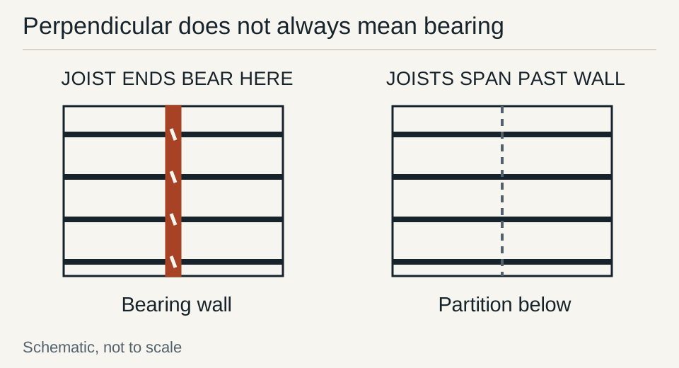
Use the following observations to prepare questions for the designer:
| Observation | What to investigate next |
|---|---|
| Joist ends meet above the wall | Identify their bearing, connection and continuity details |
| Joists continue across the wall | Determine whether the wall is an intended intermediate support |
| A beam terminates within the wall | Locate the concealed post and trace its reaction downward |
| Joists run parallel to the wall | Check for upper-wall, roof-post and lateral-bracing roles |
| A stair or large opening interrupts framing | Locate headers, trimmers and the supports carrying their reactions |
| Framing differs between adjoining rooms | Check the boundary between original construction and later work |
Follow the supports through the basement or crawlspace
A girder below the proposed wall is useful evidence of a possible load path. Establish its location relative to the wall, the direction of joists resting on it and the supports beneath it. Alignment is a reason to investigate, not a complete determination that every wall above carries structural loads.
Columns and piers transfer concentrated reactions to foundations. Their spacing is specific to the beam, load and support design. Record the actual arrangement without assuming a standard spacing. A post on a slab also raises a foundation question: the designer needs to establish whether adequate footing capacity exists beneath that location.
Pay attention where the support route changes direction or passes through a floor. Blocking, rim members, beams and connectors may transfer a reaction to a different location. They need adequate capacity and installation details. Removing a wall can concentrate a previously distributed load at a beam’s ends, so an existing foundation that worked for the wall may need a different assessment for the opening.
Record deterioration, displaced supports, unusual deflection and previous cuts for professional review. Avoid assigning a cause from a photograph. Moisture damage, settlement and changes in loading can produce similar visible symptoms but require different investigation and repair strategies.
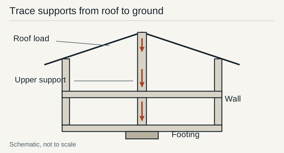
Review the roof system separately
A roof framed with individual rafters may include ridge supports, purlins, braces or other members that deliver loads to interior walls. Follow their connections and bearing points. A brace landing over a wall can be significant even when nearby ceiling joists suggest a different direction of support.
For a manufactured truss roof, obtain the truss design drawings and layout. The required bearings and reactions belong to the actual truss design. Truss length, web pattern and the presence of metal connector plates do not establish a universal rule about interior walls. Girder trusses and transitions around hips, valleys, dormers or attic rooms require particular attention.
Roof trusses also do not answer the question for a floor below. A house can have roof trusses supported at exterior walls while an interior wall supports the second floor. Review the relevant level, not just the most visible part of the roof. Altering a truss requires the appropriate engineered repair or modification detail.
Check lateral resistance as well as gravity support
Walls can resist wind and earthquake forces through braced-wall or shear-wall systems. Their role depends on the adopted code, building geometry, sheathing, connections and anchorage. An opening can interrupt that resistance even when the wall carries little gravity load.
Ask the designer to identify relevant bracing in the existing documents and inspect the affected construction. A diagonal brace, structural sheathing or hold-down connection is a reason for investigation. Decorative finishes can hide those components. Preserve their function in the proposed design instead of considering only the replacement header.
The coastal construction guide explains why the roof-to-foundation load path matters in exposed locations. Seismic and inland wind design also require continuity. The applicable design criteria come from the site and governing requirements, not from a generic description of the house as conventional framing.
Plan openings for inspection before demolition
Exploratory access should be planned by the responsible professionals with utilities and hazardous materials in mind. Electrical wiring, plumbing, gas lines and ducts can be concealed where the proposed opening would be made. In older buildings, review lead and other material hazards before disturbing finishes.
The EPA’s Renovation, Repair and Painting program generally applies to paid work disturbing painted surfaces in pre-1978 housing and child-occupied facilities, subject to its scope and exceptions. Window replacement and demolition of painted surfaces have specific treatment under those rules. Have the contractor establish the applicable lead-safe requirements before starting, rather than relying on a small opening to avoid planning.
Arrange enough access to answer the design question. Finding a double top plate, a stud pack or a single joist is not a complete structural assessment. Photograph exposed conditions with a location reference and have the designer review anything that differs from the assumed framing. Update the design before continuing with irreversible work.
Temporary support is a designed construction condition
Removing a bearing wall changes the support arrangement before the permanent beam is in place. The temporary system must carry the relevant loads while allowing safe installation. Its location, member sizes, bracing, connections, bearing surfaces and support below depend on the actual building and work sequence.
The floor beneath temporary supports is part of that assessment. Moving a reaction away from an existing wall or beam can impose loads where the floor was not designed to receive them. Support may need to continue through lower levels to an adequate foundation. Placing a post on a ceiling finish, floorboard or slab does not establish a safe load path.
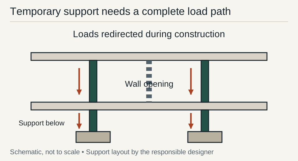
Before work starts, agree who designs the temporary system, who installs and checks it, which observations require work to stop, and when it may be removed. Existing members should remain intact until the planned support and required inspections are complete. Sudden movement, cracking or loss of support requires immediate professional attention and a safe exclusion of the affected area.
Turn the investigation into a complete remodeling scope
The final structural package should identify the wall’s function, verified framing, permanent beam and supports, connections, foundation work, temporary works and inspection stages. Coordinate electrical, mechanical and plumbing changes with that package. A flush beam and a dropped beam can require different utility routes and finish restoration.
Use the custom remodeling guide to sequence the trades and the home addition cost guide to organize a comparable scope for bids. Include investigation, permits, protection, temporary support, structural installation and restoration. The beam purchase is only one item in the work.
Retain the approved drawings and recorded changes with the property. For a future remodel, those documents are more useful than a recollection that a wall was “probably non-bearing.” They explain which supports were checked, how the final loads are carried, and what conditions the completed design relies on.
Primary Sources & Code References
- TJ-9000: beam, header, support and connection details Weyerhaeuser · reviewed October 25, 2026
- Advanced Framing: Minimal Framing at Doors and Windows U.S. Department of Energy · reviewed October 25, 2026
- Lead Renovation, Repair and Painting Program U.S. Environmental Protection Agency · reviewed October 25, 2026
- Coastal Construction Manual, Volume II, 2011 FEMA · reviewed October 25, 2026
Related Engineering Guides
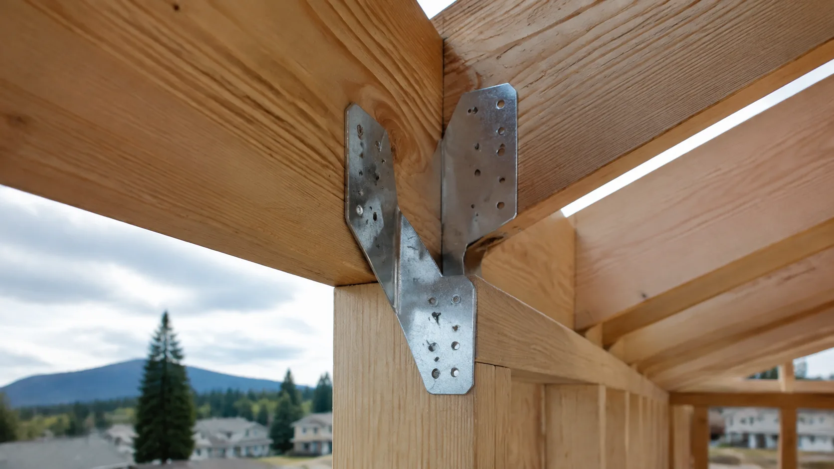
Structural Framing and Foundations: Beams, Bearing and Load Paths
Coordinate wood and steel framing, beam supports, strip and raft foundations, and wind or seismic load paths using product-specific data and site conditions.
Read technical guide LVL Beam Span Table: Microllam 2.0E Floor Loads and Header Supports
Read verified Weyerhaeuser Microllam 2.0E floor-load table entries, bearing conditions, multi-ply connections and the support checks needed for a wall opening.
Read technical guide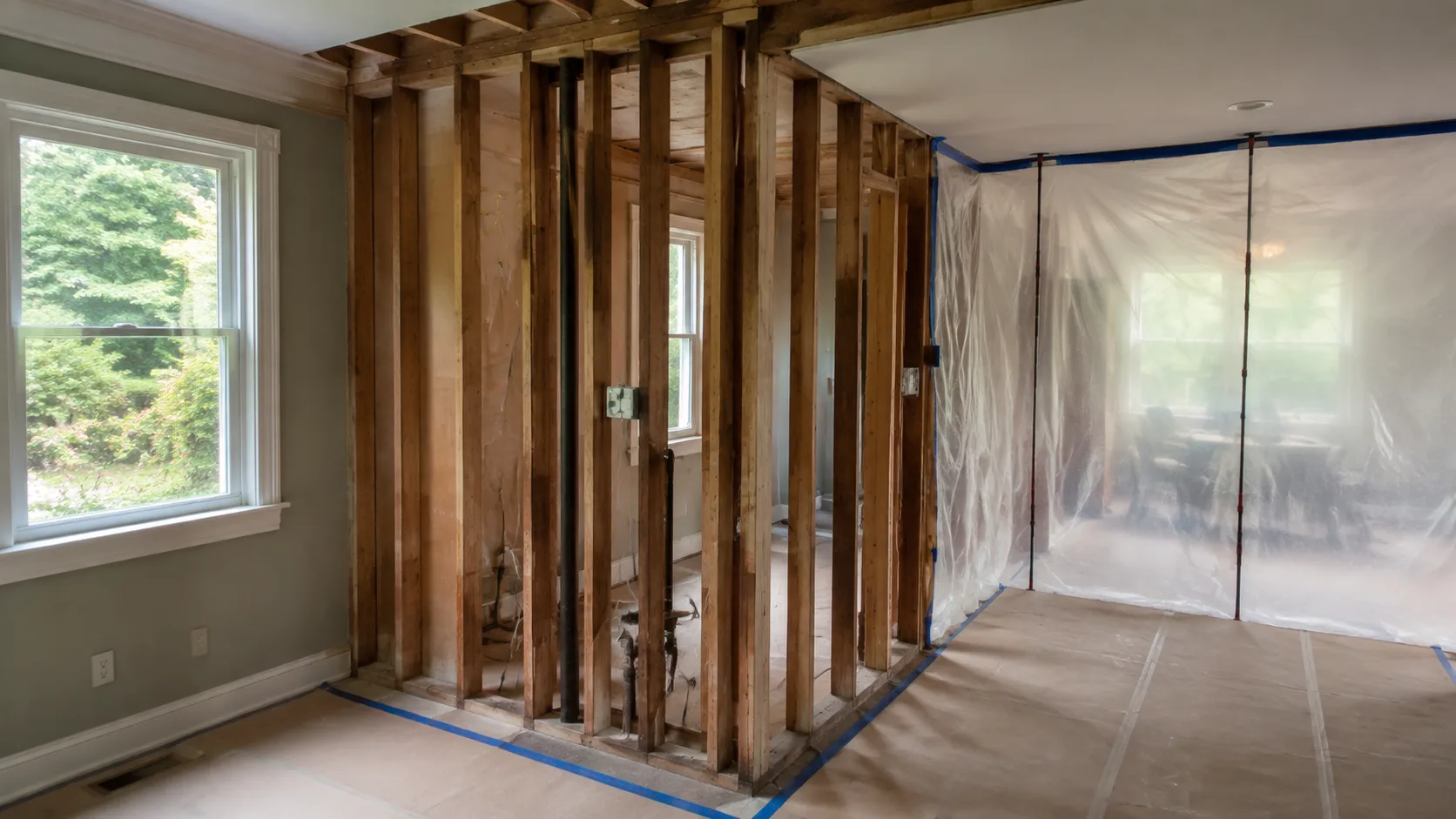
Custom Home Remodeling: Additions, Budgets and Construction Sequencing
Plan additions and kitchen or bathroom remodels with defined quantities, structural and enclosure tie-ins, permits, trade dependencies and written change control.
Read technical guide