
Structural Framing and Foundations: Beams, Bearing and Load Paths
Coordinate wood and steel framing, beam supports, strip and raft foundations, and wind or seismic load paths using product-specific data and site conditions.
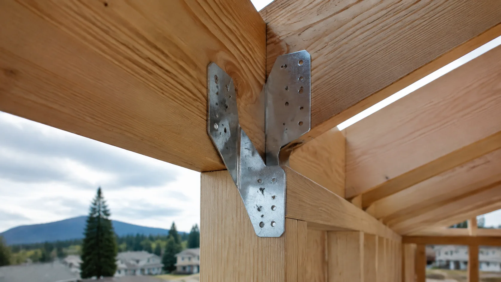
Design the frame and foundation as one load path
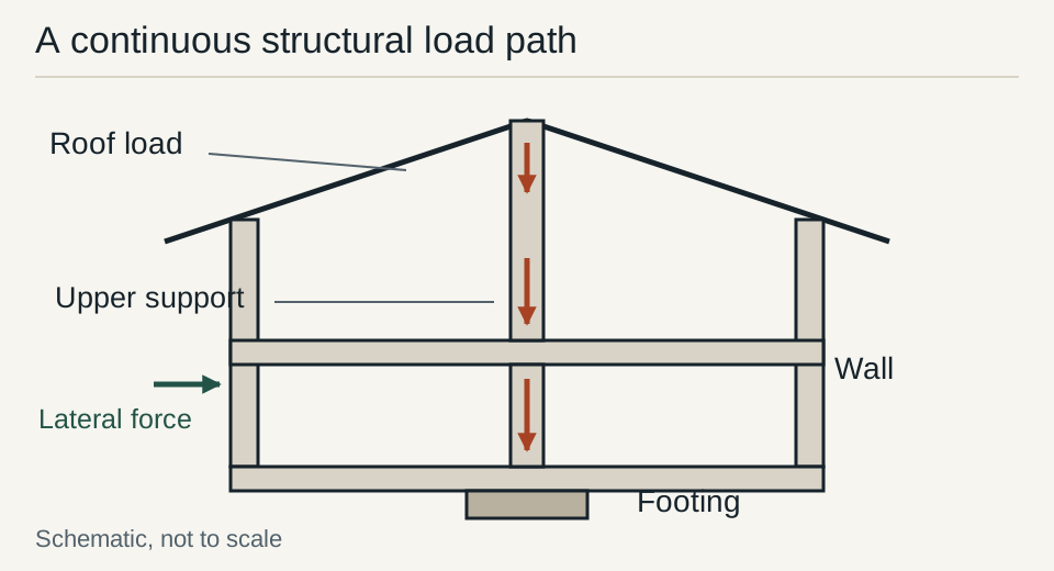
A residential structure carries gravity, wind and seismic effects through connected members into the ground. Roof coverings and framing deliver loads to walls, beams and columns; floors transfer their own loads into supports; foundations spread or transfer the resulting forces into suitable soil or deeper bearing material. Every transition needs adequate capacity and an appropriate connection.
An alteration can change that path without changing the outside of the house. Removing a wall can concentrate distributed loads at the ends of a new beam. Adding a story increases demands on existing supports. A roof replacement can change dead load and attachment requirements. Review those changes together rather than selecting a beam independently of the structure beneath it.
Start with the project’s adopted code edition, local amendments and site criteria. The 2024 IRC provides a model-code reference for residential building planning and construction, but local adoption governs. Wind exposure, snow, seismic conditions, soil, frost and flood constraints are project inputs that need verification.
The LVL beam guide provides a manufacturer-specific floor-table excerpt. The bearing-wall guide explains how to investigate existing supports. For exposed sites, also review coastal construction and flood-zone planning.
Separate the loads before selecting members
Dead load comes from permanent construction: framing, finishes, equipment and other fixed components. Establish it from the actual assembly. A tiled floor, masonry feature or rooftop installation can change the load relative to a lighter assembly. Avoid substituting a generic residential allowance for material information that the project already has.
Live loads relate to use and occupancy. Roof live load, snow, wind and seismic effects require the applicable provisions and combinations. A floor beam table should be used for matching floor conditions; roof loading needs the appropriate roof table or engineering analysis. Concentrated loads, cantilevers and continuity can require a different analysis from a uniform simple-span example.
| Design input | Information to establish | Why it matters |
|---|---|---|
| Occupancy and use | Room function and applicable live loads | Changes the loading basis for floors and supports |
| Permanent materials | Floor, wall, roof and equipment weights | Establishes dead load and its distribution |
| Framing geometry | Spans, spacing, continuity and openings | Determines tributary areas and reaction locations |
| Wind and seismic criteria | Site conditions and governing design provisions | Determines lateral resistance and connection demands |
| Foundation conditions | Soil information, water, frost and flood criteria | Determines support type and required investigation |
Record these inputs in the design documents so changes can be evaluated. A heavier finish or relocated opening should prompt a check of the affected load path, even if the framing member has already been ordered.
Light wood framing: spans, bearing and openings
Joists, rafters and studs work within a system of supports, bracing and connections. Species, grade, size, spacing and loading affect the allowable span. Engineered members add product-specific requirements for holes, bearing, blocking and lateral restraint. Match the actual member to its governing table and installation details.
At an opening, headers transfer loads to side supports. The supporting studs or columns then need a continuous route to the foundation. The presence of a header does not establish adequate bearing below it. Check the plate, floor framing and any transfer beam that receives the reaction, including changes in direction or alignment.
Joist direction helps locate potential supports but does not prove a wall’s role. Joists may span across a partition, while a parallel wall can conceal a post or resist lateral forces. Before remodeling, establish the actual bearing and bracing arrangement through drawings and professional inspection. The wall-identification guide organizes that investigation.
Engineered wood selection: use the exact product
Weyerhaeuser’s July 2026 TJ-9000 guide lists the following reference design stresses for 2.0E Microllam LVL in beam orientation at 100% load duration. These properties help explain a product table; member capacity still depends on geometry, loading, stability and the guide’s adjustment conditions.
| Property | TJ-9000 reference value | Condition to retain |
|---|---|---|
| Modulus of elasticity, E | 2.0 × 10⁶ psi | Include bending and shear deflection as the guide requires |
| Bending stress, Fb | 2,600 psi | Reference depth 12 inches; apply the guide’s depth adjustment |
| Horizontal shear, Fv | 285 psi | Use the applicable orientation and design conditions |
| Compression perpendicular to grain, Fc⊥ | 750 psi | The guide does not permit a duration-of-load increase |
The same guide identifies dry-use applications and lateral support requirements. A product stamp and full specification matter: “LVL” alone does not identify these properties. Glulam, PSL, LSL and different LVL grades have their own data. Use each manufacturer’s current documentation and any applicable evaluation report.
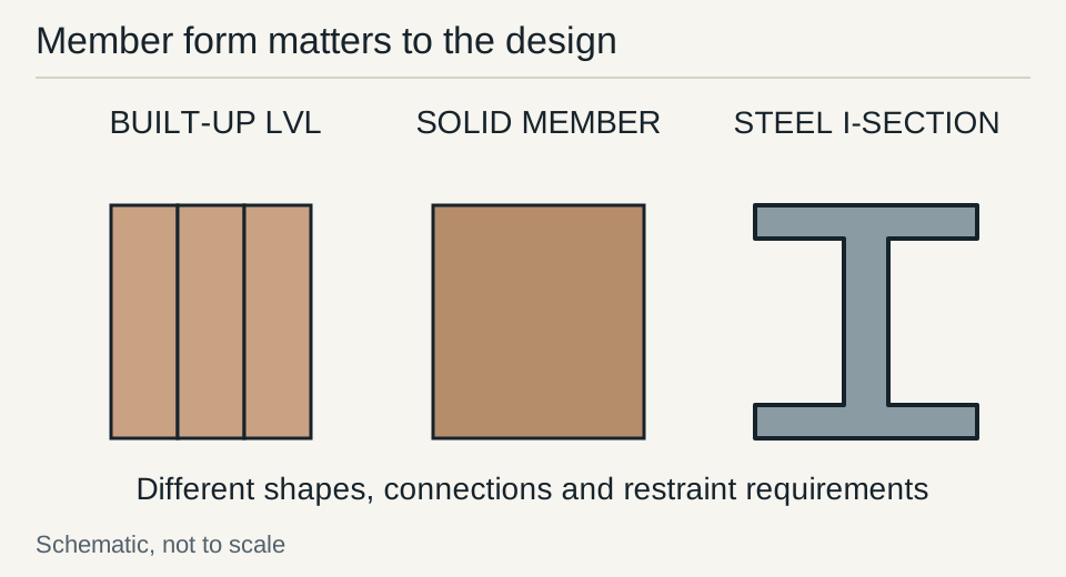
The LVL table guide transcribes total load, live load and bearing values for selected depths at a stated bearing-center span. It also explains top-loaded and side-loaded multi-ply connections. Keep these conditions together when preparing an estimate or requesting a structural design.
Steel beams and columns need a coordinated connection design
Steel may suit an opening with limited headroom or a demanding load, but the member’s depth is only one selection factor. The designer checks bending, shear, deflection, lateral stability and the actual support arrangement. Connection plates, stiffeners, bolts, welds and bearing details must fit both the structural requirements and the available construction space.
Where wood joists connect to steel, identify how their reactions enter the beam. A wood nailer, hanger or bearing arrangement has its own attachment requirements. Coordinate corrosion protection, fire protection where applicable, and access for installation and inspection. The steel fabricator should work from approved drawings that identify dimensions and connection responsibilities.
Columns require checks for compression, slenderness, restraint, base and top connections, and foundation reactions. Replacing a wall with a steel beam can increase demands on a small number of supports. Trace those reactions through the floor and foundation before assuming the new member can rest where the old wall stood.
Choose the foundation from loads and ground conditions
Foundation selection starts with site information. Establish soil and groundwater conditions, frost protection, slope and drainage, neighboring structures, and flood or erosion exposure. The local authority and design team determine the investigations needed. Soil bearing values should reflect the permitted code basis or geotechnical recommendations for the actual site.
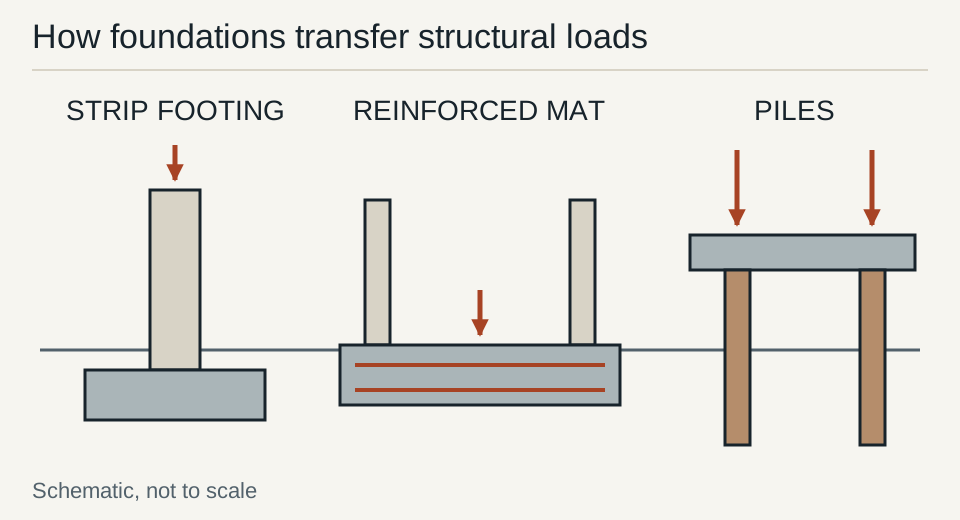
| Foundation approach | How it carries load | Questions to resolve |
|---|---|---|
| Strip footings and foundation walls | Spread wall loads along continuous footings | Soil support, footing geometry, reinforcement, drainage and frost protection |
| Isolated footings | Spread concentrated column or pier reactions | Bearing area, settlement, eccentricity and connection to the supported member |
| Slab with designed thickened supports | Integrates floor and specified bearing zones | Which portions carry structural loads and how they are reinforced |
| Raft or mat foundation | Distributes loads through a designed reinforced foundation slab | Soil interaction, stiffness, differential settlement and groundwater |
| Piles or deep foundations | Transfer loads to deeper support and resist site-specific actions | Geotechnical capacity, scour, lateral effects, uplift and connections |
A floor slab is not automatically a mat foundation. Its intended structural function must be established from drawings and investigation. Likewise, selecting a wider footing by rule of thumb does not resolve settlement, water or unsuitable fill. The design must address the relevant failure modes and construction conditions.
Coordinate drainage, moisture and foundation durability
Structural capacity and moisture control belong in the same foundation review. Grade, roof drainage, perimeter drainage where required, waterproofing or dampproofing, capillary breaks and ground vapor control need compatible details. Water should be managed without undermining support or directing concentrated flow toward neighboring property.
Crawlspace and basement approaches differ with climate, site and intended use. Coordinate enclosure details and mechanical systems so the space can be maintained as designed. The building-envelope guide explains continuity between the foundation, wall and roof control layers; the moisture guide addresses humidity and drying concerns.
For coastal sites, FEMA’s Coastal Construction Manual, Volume II, provides background on design and construction under wind and flood hazards. Its 2011 publication date should be considered alongside the current adopted requirements. Project-specific flood elevations, wave conditions, erosion and scour can govern foundation form and the permitted use of lower spaces.
Wind and seismic resistance extend beyond individual connectors
The lateral system can include roof and floor diaphragms, braced or shear walls, collectors and anchorage. These components transfer forces through the building. Openings, offsets and changes in stiffness can affect that route. A stronger roof connector does not by itself establish an adequate lateral system below it.
For a remodel, identify the bracing role of affected walls before removing finishes or framing. The designer should evaluate the proposed openings and provide the required replacement resistance and connections. Seismic requirements depend on the applicable design category and building conditions; retain those project criteria with the approved design.
During construction, inspect critical connections before concealment. Match connector models and fasteners to the approved details. Substituting a nearby screw or omitting a required fastener can change the connection capacity. Record approved substitutions and corrections rather than leaving them to later recollection.
Construction hold points and owner records
Agree on the sequence for excavation review, reinforcement and embeds, concrete placement, framing supports, connections and concealed work inspections. Assign responsibility for each check and identify the documents needed to proceed. Temporary excavation support, shoring and weather protection should be planned for the actual construction condition.
For an alteration, confirm the exposed framing matches the design assumptions before cutting. Stop and obtain a revised detail when unexpected supports, damage or utilities affect the work. The remodeling guide connects this process to trade coordination and change control.
At closeout, retain approved structural drawings, geotechnical information where obtained, inspection records, product documents and accepted changes. These records help future designers understand the building’s support system and avoid repeating investigations or relying on unsupported assumptions about concealed construction.
Primary Sources & Code References
- TJ-9000 Beam, Header and Column Specifier’s Guide, July 2026 Weyerhaeuser · reviewed October 25, 2026
- Coastal Construction Manual, Volume II, 2011 FEMA · reviewed October 25, 2026
- 2024 International Residential Code International Code Council · reviewed October 25, 2026
Related Engineering Guides
LVL Beam Span Table: Microllam 2.0E Floor Loads and Header Supports
Read verified Weyerhaeuser Microllam 2.0E floor-load table entries, bearing conditions, multi-ply connections and the support checks needed for a wall opening.
Read technical guide
Load-Bearing Wall Identification: Joists, Basement Supports and Roof Loads
Trace joist bearing, basement supports, roof reactions and lateral bracing before planning a wall opening, with the checks needed for temporary support.
Read technical guide
Coastal Building Guide
A practical starting point for planning durable homes in hurricane, flood, salt-air, and hot-humid coastal conditions.
Read technical guide