
Exterior Siding and Roofing: Drainage, Cladding and Roof Details
Compare fiber-cement, metal and vinyl siding, roof coverings and the flashing connections that keep rain, air and moisture control continuous.
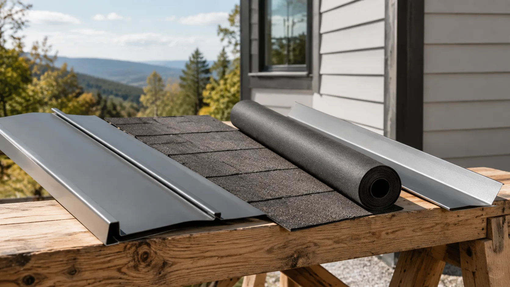
Connect roofing and siding through their water-control details
The visible roof and cladding shed much of the rain that reaches a house. Water that passes those outer layers still needs a controlled route outward. Roof underlayment, wall water-resistive barriers, flashings and drainage spaces must connect at eaves, windows, doors, penetrations and roof-to-wall junctions.
Start with an assembly drawing rather than a list of finish products. Identify which layer controls rain, air leakage, vapor diffusion and heat flow. One material may perform more than one function, and the order of layers depends on the assembly and climate. A wall’s air barrier, for example, can be located at a different plane from its primary water-resistive layer.
Use the building-envelope guide to trace those functions around the house. The ice-barrier guide develops the eave and valley details, while the standing-seam comparison examines specific roof products and their wind documentation.
Four control functions to resolve
| Function | Design question | Detail to coordinate |
|---|---|---|
| Rain control | Where does water go after passing the finish? | Continuous drainage plane and flashing outlets |
| Air control | Where is the continuous air barrier? | Joints, penetrations and transitions between assemblies |
| Vapor control | How can materials dry in this climate? | Material permeance, vapor-retarder location and adjacent layers |
| Thermal control | Where does insulation remain continuous? | Framing bridges, openings, roof edges and foundations |
These functions work together. Air leakage can transport moisture into a cold assembly; a water leak can wet insulation; a low-permeance replacement layer can reduce drying. Review changes with the whole enclosure rather than assuming that adding another membrane always improves performance.
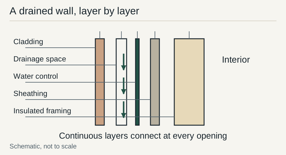
For existing homes, establish what is already installed before designing an overlay. Old siding, sheathing, insulation and interior finishes affect the available drying paths. The hot-humid moisture guide is useful when cooling and inward vapor drive influence the design.
Choose siding as a complete installed system
Fiber-cement, metal and vinyl siding have different fastening, movement, finish and maintenance requirements. Compare the exact product instructions, not just the appearance of samples. The substrate, supporting furring, fastener corrosion resistance, wind rating and required clearances belong in the specification.
| Cladding type | Installation questions | Durability questions |
|---|---|---|
| Fiber cement | Required backing, fastening, joints, cut-edge treatment and clearances | Paint or finish care, moisture exposure and replacement access |
| Metal panels | Panel profile, support spacing, movement provision and compatible accessories | Coating limits, cut edges, corrosion and dissimilar-metal contact |
| Vinyl siding | Nailing-slot use, movement allowance, trim and substrate | Thermal movement, impact damage and replacement matching |
Use the manufacturer’s current guide for dimensions and details. A clearance suitable for one fiber-cement product is not automatically the rule for all claddings. A metal panel’s gauge does not establish its wall span or wind capacity without the corresponding profile, support and attachment information.
For vinyl, fastening should permit the movement required by the product rather than pinning the siding rigidly to the wall. For metal, the selected system may use clips, slotted connections or other movement details. For fiber cement, joint treatment and fastening depend on the product and installation method. Require those distinctions in the contractor’s scope.
Drainage cavities need an inlet, an outlet and continuity
A cavity behind cladding can separate the finish from the drainage plane and provide a route for water to leave. Its dimensions and ventilation provisions depend on the product, wall design and applicable requirements. Furring direction, blocking and insect screens should preserve the intended drainage path.
Horizontal obstructions can interrupt vertical drainage. At windows, floor lines and changes in cladding, show how water passes the obstruction or exits over a flashing. A nominal gap in the middle of the wall is of little help if it terminates in a closed pocket at the bottom.
The water-resistive barrier should be integrated with flashings in water-shedding order. Select tapes, sealants and membranes that are compatible with the substrate and one another. Check temperature, moisture and preparation conditions before installation. Product substitution needs review at the junctions where different materials meet.
Window and door openings: connect the flashing to the wall
An opening interrupts several control layers. The sill needs a drainage strategy; jamb and head details need to shed water into the intended drainage plane; the interior air seal needs continuity with the wall air barrier. Follow the window and flashing manufacturers’ compatible installation details.
At the head, arrange the upper wall drainage plane to discharge over the head flashing where the selected detail requires it. At the sill, preserve the intended outlet rather than sealing every edge indiscriminately. Identify back dams, end dams and corner treatment in the approved detail. The appropriate arrangement depends on the opening, flange and wall system.
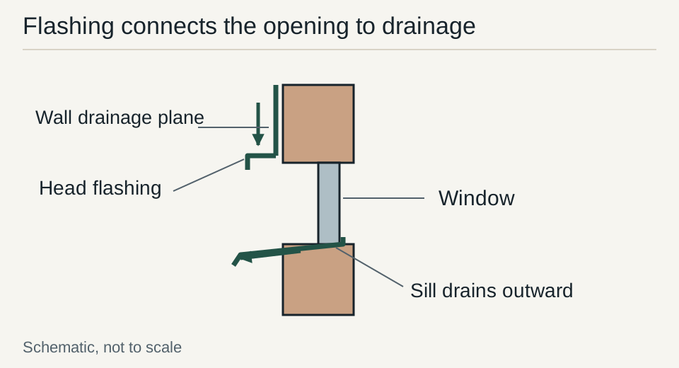
A mockup can resolve the installation sequence before the same detail is repeated across the house. Include the actual window, wall layers, fasteners and flashing products. Agree what is being checked and who approves the detail. Photograph the accepted sequence while the layers are visible.
Roof coverings have product-specific slope and attachment limits
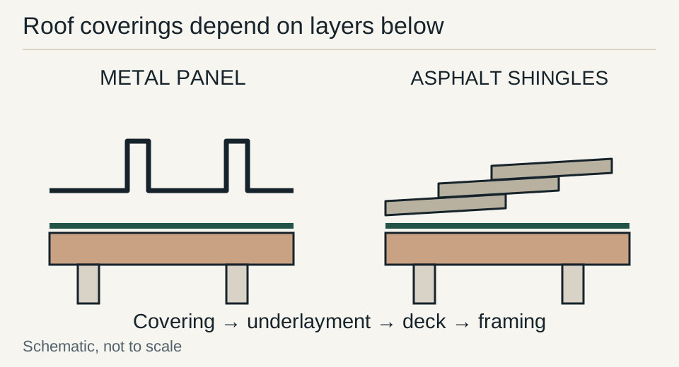
Architectural asphalt shingles and standing-seam panels require different installation details. Confirm the roof slope, substrate and named covering before selecting underlayment or pricing accessories. The governing code and the manufacturer’s instructions must both be considered.
As representative examples, McElroy’s Medallion-Lok is a clip-attached snap-lock standing-seam panel, while its Meridian panel uses a concealed fastening flange. Both published product pages specify a 3:12 minimum slope, despite broader model-code provisions for some other standing-seam assemblies. The roof comparison explains why the specific profile matters.
A shingle wind classification and a metal assembly test are not interchangeable measures. Require the actual product classification or assembly report and have the designer compare it with the project’s requirements. Review the deck, attachment, edge metal and roof-to-wall load path together, particularly in exposed locations.
Eaves, valleys and roof-to-wall intersections
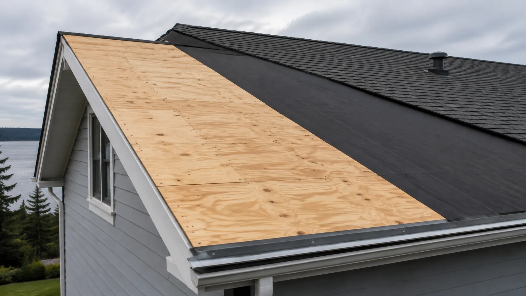
Where the adopted ice-barrier provisions apply, establish the required coverage from the actual eave and exterior-wall geometry. The 2024 IRC model provision includes the interior wall-line distance and a separate steep-slope provision. Use the ice-barrier guide for those measurements and product-specific membrane laps.
Valleys collect runoff from two roof planes and need an assembly compatible with the covering. At roof-to-wall intersections, connect the roof flashing with the wall drainage plane. A kickout diverter at the lower sidewall termination helps direct concentrated runoff away from the siding and into the intended drainage route.
Chimneys, skylights and other penetrations require their own details. Coordinate the upslope diversion, side flashings and lower discharge. Avoid treating surface sealant as a substitute for a durable layered connection. Include access for later inspection and replacement in the design.
Select underlayment for temperature and compatibility
A high-temperature membrane is selected by its named product data and the roof assembly’s requirements. GCP’s cited GRACE ICE & WATER SHIELD HT sheet lists resistance up to 260°F (127°C), along with installation and material-compatibility restrictions. That value should not be extended to every underlayment or used as a universal roof-deck temperature prediction.
The panel manufacturer may require a particular underlayment, separation layer or ventilation arrangement. Confirm compatibility with the metal, adjacent membranes, treated materials and sealants. Transitions to a different roofing system deserve explicit review because the products may have different chemical and drying behavior.
Full-deck self-adhered coverage can reduce drying through the roof. Coordinate it with insulation, air control and ventilation. The appropriate design depends on climate and the full roof section; a roof upgrade should not unintentionally trap construction moisture or conceal an unresolved leak.
Coordinate corrosion, fasteners and exposed accessories
Exterior durability depends on the compatibility of fasteners, connectors, flashings and cladding. Coastal salt, treated wood, runoff from dissimilar metals and persistent wetting can affect those choices. Use product instructions and the project’s exposure assessment to select compatible materials and coatings.
Ask suppliers to address contact and runoff paths, not just direct metal-to-metal contact. A flashing above a different metal can carry contaminated runoff onto it. Also identify how cut edges and damaged coatings are repaired and how future maintenance can reach the relevant details safely.
The building materials guide provides a comparison framework. For coastal work, FEMA’s Coastal Construction Manual offers background on environmental exposure and durable construction, alongside current local requirements and manufacturer documentation.
Inspection stages before the finish hides the work
Check substrates and framing repairs before membranes are installed. Review air and water-control continuity before cladding covers it. Inspect openings, roof edges, valleys and penetrations at the stages when their connections can still be corrected. Assign responsibility and documentation requirements before work starts.
For reroofing or siding replacement, include a process for concealed damage discovered after removal. The contractor should identify the affected area, obtain the necessary review and document approved repairs before closing it. The remodeling guide connects these discoveries to pricing and schedule changes.
At handover, retain product instructions, warranties, accepted details and concealed-work photographs. Provide a maintenance plan covering drainage, joints, roof transitions and safe access. Later additions, solar installations or equipment penetrations should be reviewed against the completed enclosure so new work preserves the intended control layers.
When comparing bids, require each contractor to identify the same opening and roof-transition details. An excluded flashing repair can make a lower price appear more complete than it is.
Primary Sources & Code References
- Metal Roofs U.S. Department of Energy · reviewed October 25, 2026
- Roof Eaves Sealed with Self-Adhering Membrane U.S. Department of Energy · reviewed October 25, 2026
- Coastal Construction Manual, Volume II, 2011 FEMA · reviewed October 25, 2026
- Medallion-Lok specifications McElroy Metal · reviewed October 25, 2026
- GRACE ICE & WATER SHIELD HT Data Sheet GCP Applied Technologies · reviewed October 25, 2026
Related Engineering Guides
Ice and Water Shield: IRC Eave Coverage, Valleys and Product Selection
Apply the 2024 IRC ice-barrier scope and eave geometry, coordinate valley and drip-edge laps, and compare GRACE HT product conditions for the roof assembly.
Read technical guide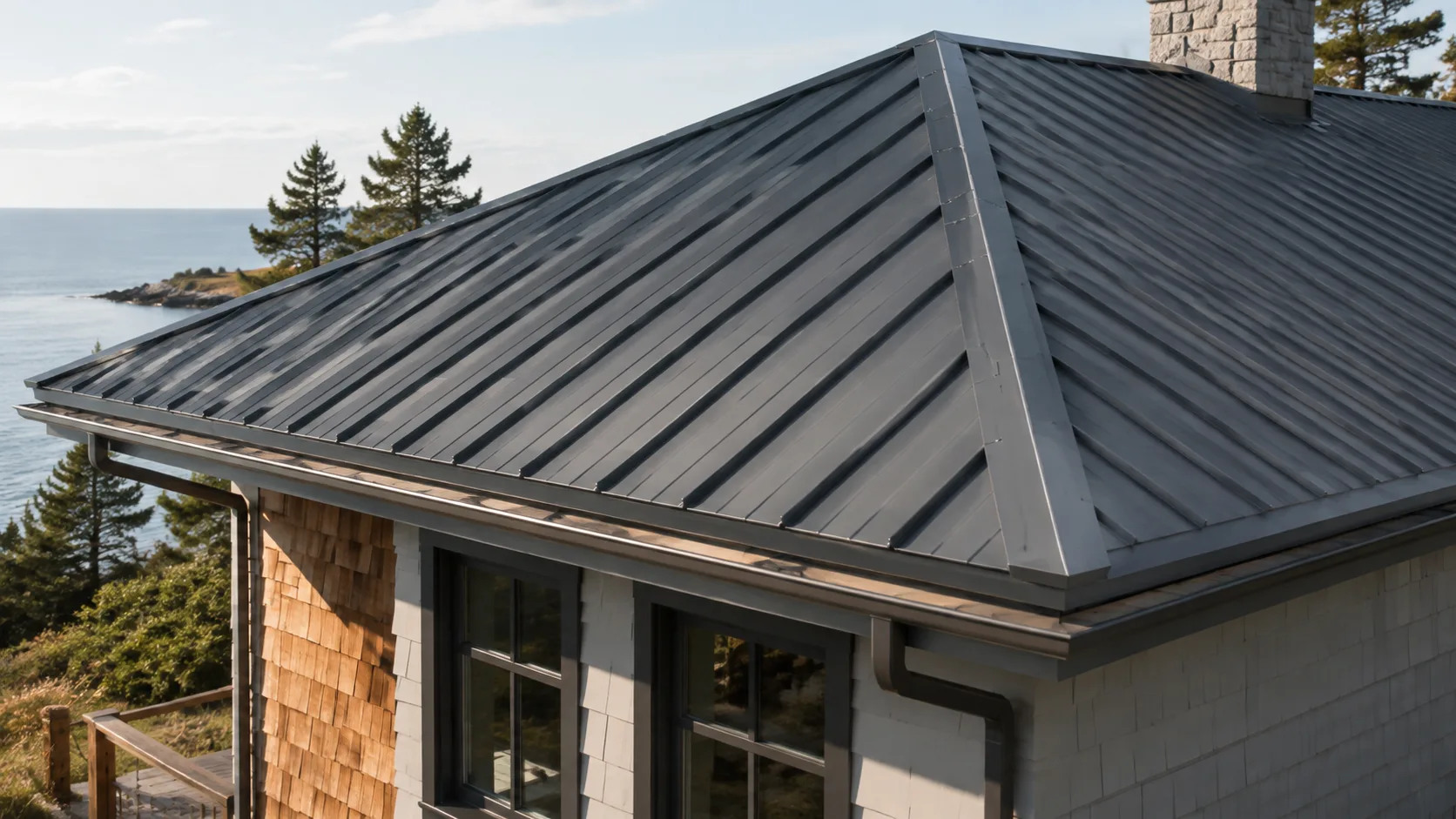
Standing Seam Metal Roof vs. Shingles: Wind, Service Life and Ownership Cost
Compare named metal and shingle specifications, attachment methods, wind-test conditions, warranties and a project-based 50-year ownership-cost framework.
Read technical guide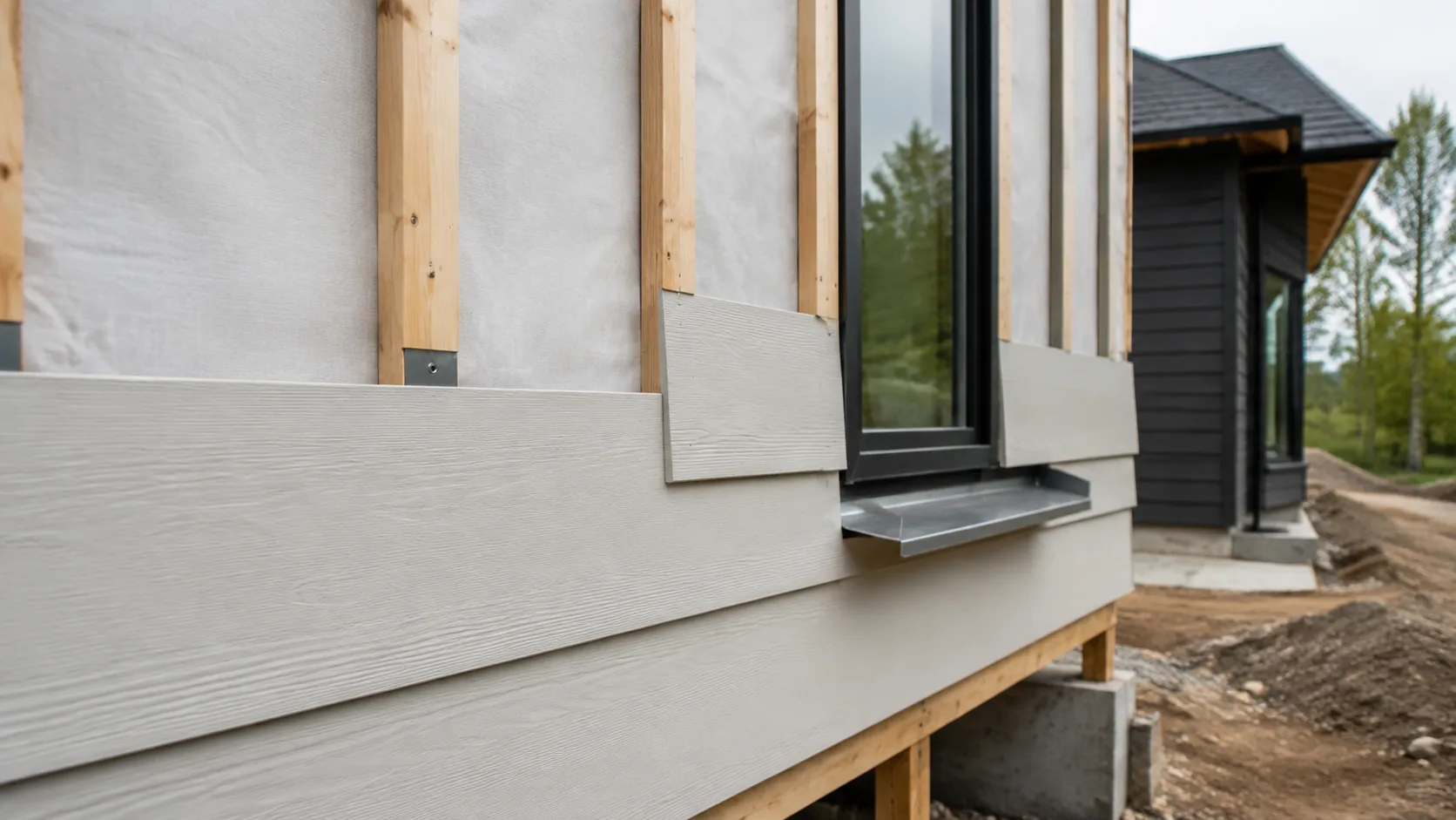
Building Envelope Guide
Understand how roofs, walls, windows, foundations, air barriers, drainage planes, insulation, and HVAC work as one enclosure.
Read technical guide