
LVL Beam Span Table: Microllam 2.0E Floor Loads and Header Supports
Read verified Weyerhaeuser Microllam 2.0E floor-load table entries, bearing conditions, multi-ply connections and the support checks needed for a wall opening.
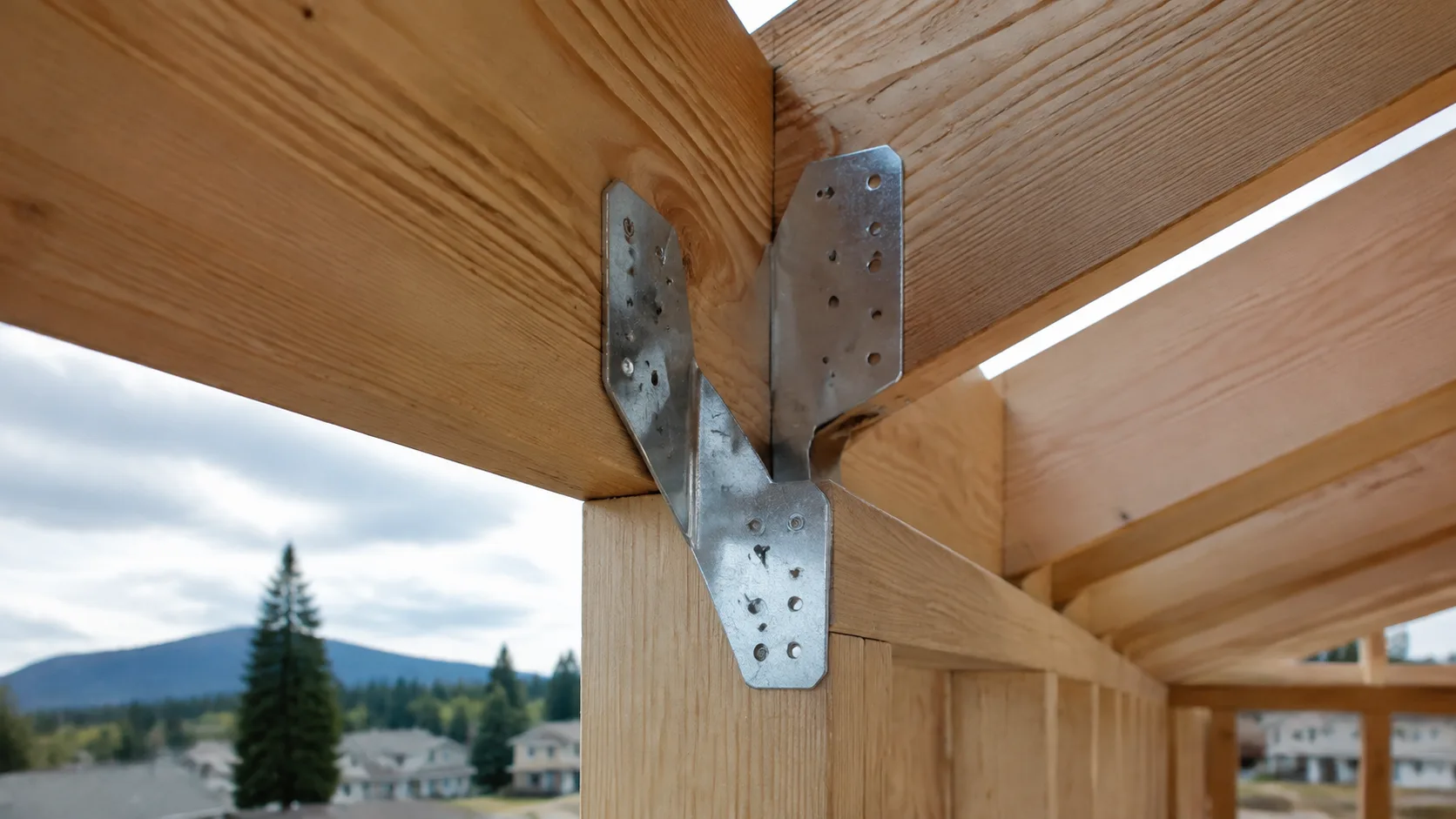
Start with the product stamp and the load path
An LVL beam span table answers a specific question: how much load a particular product, width and depth can carry under the conditions stated by its manufacturer. The opening width alone does not select the beam. A replacement header also changes where loads enter the floor and foundation below. Resolve both questions before ordering lumber or removing framing.
This guide uses Weyerhaeuser 2.0E Microllam LVL, in the July 2026 TJ-9000 Beam, Header and Column Specifier’s Guide. Its floor tables separate total load, live load and bearing length. Those values belong together. Another manufacturer’s 2.0E product can have different strength, bearing and connection properties even when the stiffness designation looks the same.
Begin with the load-bearing wall investigation, then connect the proposed opening to the foundation and framing system. A beam that passes a bending check still needs adequate supports, connections and lateral restraint. Have the responsible designer resolve the existing loads and temporary support before demolition.
Establish the loading before using a table
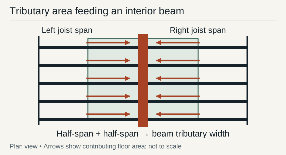
Distinguish an area load, expressed in pounds per square foot, from a beam line load, expressed in pounds per linear foot. For simply supported joist spans bearing on opposite sides of an interior beam, the tributary width is half the left span plus half the right span. Multiplying that width by an applicable uniform area load gives the corresponding uniform beam load.
Uniform line load = tributary width × area load. Keep the live and dead components separate. The designer determines the dead load from the actual materials, and the live load from the occupancy and governing code. Roof snow, roof live load, wind effects and load combinations require their own assessment. A floor table is appropriate only after the floor-loading conditions match its scope.
A wall above, stair opening, interrupted joist, girder truss or roof post may introduce concentrated loads. Continuous joists and beams can also have reactions that differ from the simple tributary approximation. Record those conditions on the framing sketch rather than converting everything into an average line load. The location of a point load matters as well as its magnitude.
Verified floor-load reference: 12-foot bearing-center span
The following excerpt transcribes TJ-9000 pages 8–9, under “2.0E Microllam LVL: Floor—100% (PLF).” The span is 12 feet, center-to-center of bearing, rather than the clear distance between support faces. Each ply is 1¾ inches wide. Two plies make a 3½-inch member; three plies make a 5¼-inch member.
| Depth | Plies / width | Total load, PLF | Live load at L/360, PLF | Minimum end / intermediate bearing, inches |
|---|---|---|---|---|
| 9¼ in. | 2 / 3½ in. | 548 | 372 | 1.5 / 3.5 |
| 9¼ in. | 3 / 5¼ in. | 823 | 558 | 1.5 / 3.5 |
| 11⅞ in. | 2 / 3½ in. | 979 | 758 | 2.3 / 5.7 |
| 11⅞ in. | 3 / 5¼ in. | 1,469 | 1,137 | 2.3 / 5.7 |
| 14 in. | 2 / 3½ in. | 1,333 | 1,198 | 3.1 / 7.7 |
| 14 in. | 3 / 5¼ in. | 2,000 | 1,797 | 3.1 / 7.7 |
| 16 in. | 2 / 3½ in. | 1,709 | Total load controls | 3.9 / 9.9 |
| 16 in. | 3 / 5¼ in. | 2,563 | Total load controls | 3.9 / 9.9 |
Conditions of the excerpt: uniform loads; beam weight considered by the table; the more restrictive of simple or continuous span; L/240 total-load and L/360 live-load deflection criteria; 100% load duration. For continuous spans, TJ-9000 requires a short-span/long-span ratio of at least 0.4 to prevent uplift. Read its general assumptions on page 5 with the table: dry-use application, lateral support at bearings and along the span at a maximum of 24 inches on center, and the manufacturer’s alignment requirements.
Both load checks must pass. Compare the project’s total uniform load with the total column and its live load with the live column. “Total load controls” is the manufacturer’s asterisk notation; it does not remove the need to establish the actual loads. The bearing values are part of this particular table row, not universal support dimensions for that beam depth.
For other spans, use the matching rows of the linked original guide. Record the exact row, member size and all table notes in the design documentation. Do not interpolate a missing span without the designer’s approval. The roof tables use different loading conditions and occupy separate sections of TJ-9000.
Bearing length is only one part of support design
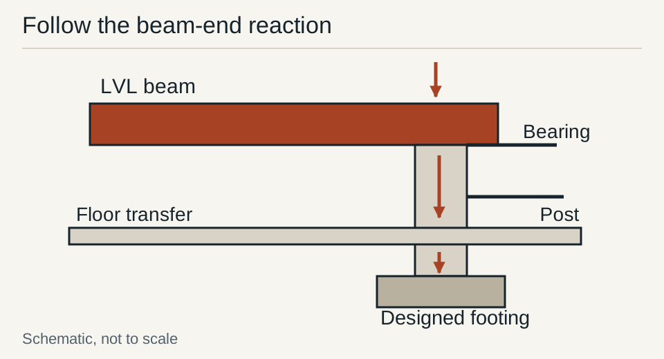
The beam’s end reaction must travel through its bearing surface, supporting studs or column, floor system and foundation. The minimum bearing length shown above addresses the manufacturer’s beam-table conditions. It does not determine the capacity of the supporting wall plate, the column, its bracing or the soil beneath a footing.
For a simply supported beam carrying only a uniform load, each reaction is one-half of the total applied load. Other support arrangements and loading patterns require their own reaction calculation. Once the reactions are known, the designer checks crushing at bearing interfaces, compression and stability of posts, connections, and the supporting foundation. A finish slab should not be treated as a footing merely because a post can physically stand on it.
The required jack-stud count follows those checks. Stud species, grade, dimensions, unsupported height and how the load spreads into the plate all matter. King studs have a different framing role and do not automatically add vertical bearing area under the beam. Where an opening moves the reactions away from existing foundation supports, the design may need a new support route through the lower floor.
Multiple plies: distinguish top loading from side loading
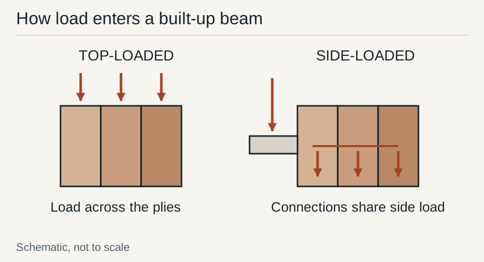
A built-up beam needs a connection design that transfers load between plies. For a beam loaded across its top, use the manufacturer’s top-loaded member details. A flush beam with joist hangers on one face is side-loaded: the outer ply receives load that the connection must distribute to the remaining plies. A screw’s length alone does not establish that transfer capacity.
TJ-9000 page 28, detail L17, gives maximum uniform load applied to either outside member for named assemblies and fasteners. For example, its two-row, 12-inch-on-center entry for 10d nails measuring 0.128 × 3 inches, or 0.131 × 3 inches, gives 370 PLF for Assembly A (two 1¾-inch plies) and 280 PLF for Assembly B (three 1¾-inch plies). The two-row entry is limited to beams up to 14 inches deep. Placement must follow the illustrated assembly; these are connection capacities, separate from the beam capacities above.
Bolts and proprietary screws occupy different rows. The A307 half-inch through-bolt option has its own depth, hole, washer and end-distance conditions. The guide requires at least 9¼-inch beam depth for that bolt entry, holes no larger than 9/16 inch and washers; counterbored installations are excluded. Its general side-loaded connection notes specify a six-inch minimum end distance for bolts and screws. Have the designer select the actual row and show its complete fastening layout on the drawings.
Coordinate a dropped or flush beam with the existing house
A dropped beam sits below the joists; a flush beam fits into their depth and commonly requires hangers at interrupted joists. Headroom, utilities, connection access and the support arrangement influence that choice. Neither configuration can be selected solely from a preferred ceiling appearance. The designer must confirm how every affected joist is supported during and after the work.
Before pricing the change, identify electrical circuits, ducts, drains and water lines near the proposed beam. Route services around the engineered member using approved details. Drilling, notching and tapered cuts have product-specific limits; a hole permitted in a nearby I-joist is not permission to cut an LVL beam. Refer the proposed penetration to the responsible designer and the manufacturer’s applicable detail.
The remodeling planning guide connects this structural work to permits, trade sequencing and occupied-home protection. Include investigation, temporary works, foundations, connections and finish restoration in the addition budget. Pricing only the lumber leaves much of the opening’s actual scope unresolved.
Documents to agree before removing the wall
Ask for a drawing that identifies the beam’s manufacturer, grade, ply count, depth, span definition, loads, reactions, support dimensions, connection schedule and lateral restraint. It should show where the forces reach the foundation and which existing conditions must be verified before proceeding. Temporary support and its removal sequence belong in the construction plan, with responsibility assigned to qualified professionals.
At delivery, match the product stamp and dimensions to the approved design. Inspect damage and storage conditions before installation. Before concealment, check the installed bearing, connections and support route against the drawings and required inspections. Retain the product documentation and approved changes with the property records so later alterations can be assessed against what was actually installed.
Check substitutions against the whole design
A supplier may offer a different brand, grade or number of plies when the specified member is unavailable. Send the proposed substitution to the responsible designer before purchase. Compare its bending, shear, deflection, bearing and connection requirements with the approved design, including dimensions that affect hangers and finishes. Keep the accepted substitution with the drawings so the installer and inspector work from the same specification.
Primary Sources & Code References
- TJ-9000 Beam, Header and Column Specifier’s Guide, July 2026, pp. 5, 8–9, 28–30 Weyerhaeuser · reviewed October 25, 2026
Related Engineering Guides
Structural Framing and Foundations: Beams, Bearing and Load Paths
Coordinate wood and steel framing, beam supports, strip and raft foundations, and wind or seismic load paths using product-specific data and site conditions.
Read technical guide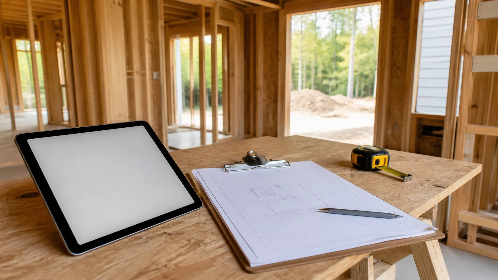
Load-Bearing Wall Identification: Joists, Basement Supports and Roof Loads
Trace joist bearing, basement supports, roof reactions and lateral bracing before planning a wall opening, with the checks needed for temporary support.
Read technical guide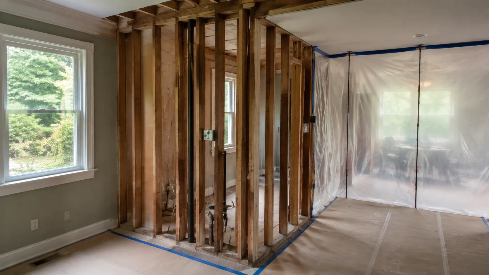
Custom Home Remodeling: Additions, Budgets and Construction Sequencing
Plan additions and kitchen or bathroom remodels with defined quantities, structural and enclosure tie-ins, permits, trade dependencies and written change control.
Read technical guide