
Ice and Water Shield: IRC Eave Coverage, Valleys and Product Selection
Apply the 2024 IRC ice-barrier scope and eave geometry, coordinate valley and drip-edge laps, and compare GRACE HT product conditions for the roof assembly.
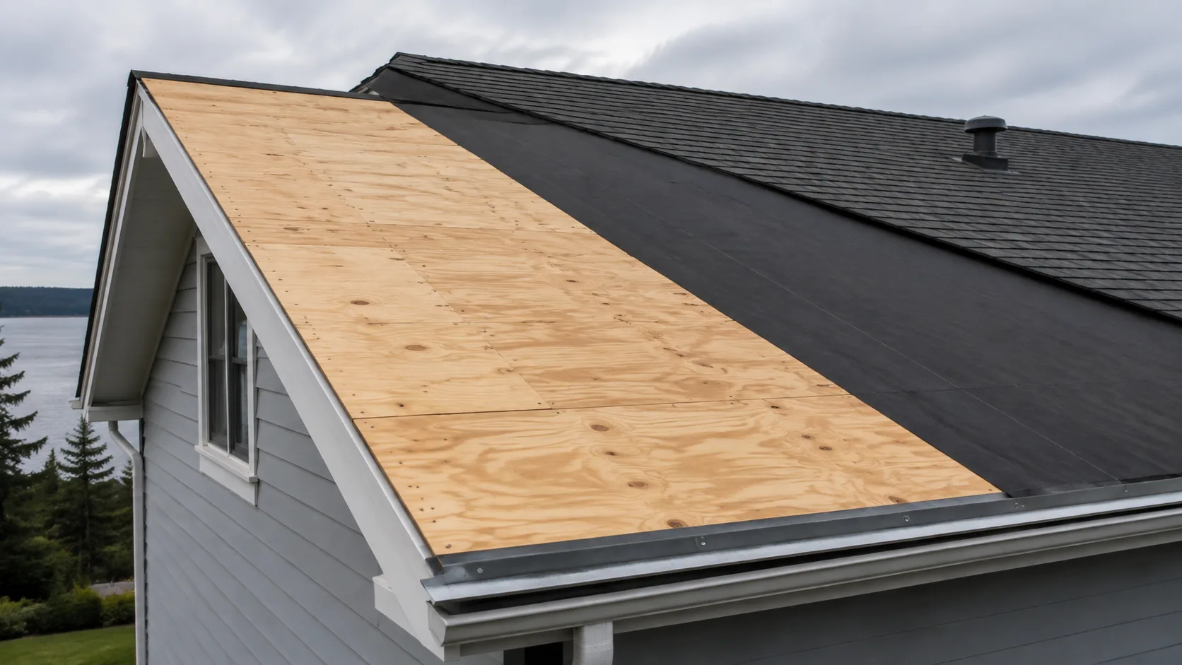
First establish whether the ice-barrier rule applies
Ice barriers protect vulnerable roof areas where water can back up beneath the covering. An ice dam can form when snow melts higher on the roof and refreezes at a colder eave. The underlayment helps resist the resulting water entry, while roof insulation, air sealing and ventilation address conditions that contribute to ice-dam formation.
2024 IRC R905.1.2 applies in areas designated in Table R301.2 as having a history of ice forming at eaves and causing water backup. Its listed coverings include asphalt shingles, metal roof shingles, mineral-surfaced roll roofing, slate and slate-type shingles, wood shingles and wood shakes. Detached accessory structures without conditioned floor area have an exception. Standing-seam metal panels need their applicable roof-panel provisions and manufacturer instructions checked separately.
The IRC is a model code. The legally adopted edition, amendments and local climatic designation determine the requirement for a project. Confirm these with the building department before measuring membrane quantities. A contractor’s standard allowance of one roll course should follow that assessment, rather than substitute for it.
Read this guide alongside exterior siding and roofing, the standing-seam comparison and the high-wind roof guide. Ice backup, wind-driven rain and uplift are related roof risks, but each needs its own detailing and compliance checks.
Measure coverage from the exterior wall line
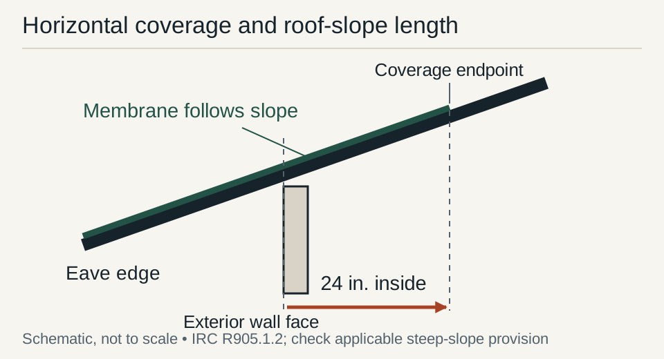
R905.1.2 describes an ice barrier extending from the lowest roof edges to at least 24 inches inside the exterior wall line. It permits two underlayment layers cemented together or a self-adhering polymer-modified bitumen sheet in place of ordinary underlayment. For roofs at 8:12 or steeper, the section separately states a minimum 36 inches measured along the slope from the eave edge. Include the applicable steep-slope provision in the approved roof detail.
The horizontal reference and the slope measurement are different. Measure the actual roof edge, exterior wall reference and slope on the project drawing. If H is the horizontal distance from that edge to the required coverage endpoint and p is the roof rise per 12 units of run, the corresponding slope length is:
Slope length = H × √(1 + (p/12)²).
Use consistent units. The actual wall and overhang dimensions define H; adding an assumed wall thickness to every roof can move the reference incorrectly. Have the designer or building official resolve the exterior-wall reference in the approved detail. Measure the steeper-roof minimum along the deck as the section requires.
Convert the required coverage into membrane courses
The number of courses depends on roll width, required slope coverage and the selected product’s side laps. For a roll width W and a side lap s, successive courses add W − s of coverage after the first full course. Determine the total net coverage on the roof detail and allow for corners, valleys, penetrations and waste separately.
For GRACE ICE & WATER SHIELD HT, the cited GCP data sheet specifies a 36-inch roll width, a minimum 3.5-inch side lap, and a minimum 6-inch end lap. Those dimensions belong to this product. Side laps between courses and end laps joining lengths of membrane perform different jobs; using the same assumed overlap for both can create a deficient installation.
Avoid treating a roll’s gross square footage as the installed coverage. Laps consume material, and a roof with valleys and interruptions has different quantities from a simple rectangular eave. Show the coverage endpoint and course layout on the estimate. This makes it possible to compare bids and inspect the work while the membrane is visible.
Prepare the deck and plan safe access
A self-adhered membrane needs a suitable substrate. GCP’s sheet calls for a clean, dry, continuous structural deck, with damaged and unsupported areas repaired before application. Dust, moisture and uneven surfaces can impair adhesion. Check the actual substrate against the selected product’s preparation and priming requirements.
For the cited HT product, the air, roof deck and membrane must be at least 40°F (5°C) during application. Follow the manufacturer’s weather and application conditions rather than relying only on an afternoon forecast. The temperature of a shaded deck or stored roll may differ from the surrounding air.
Roof work requires suitable fall protection and trained installers. Membranes and release liners can be slippery; keep liners out of walking routes. Arrange temporary weather protection and enough work time to close vulnerable areas. A partial membrane installation should not be assumed to protect unfinished roof-to-wall details or openings during a storm.
Eave and rake drip-edge laps need a coordinated detail
For asphalt-shingle roofs, the 2024 IRC R905.2.8.5 model detail places underlayment over the eave drip edge and beneath the rake drip edge. That arrangement helps water leave the roof at the eave while the rake edge covers the side termination. Local amendments and the selected roofing assembly can affect the permitted detail.
Do not automatically substitute “self-adhered ice barrier” for every reference to underlayment. The cited GCP HT sheet instructs installers to place metal drip edges over its membrane. Resolve the membrane, drip edge and field-underlayment sequence together using the manufacturer’s approved detail and local requirements. Where instructions appear to differ, obtain the accepted detail before construction, including any additional membrane strip or transition required by the supplier.
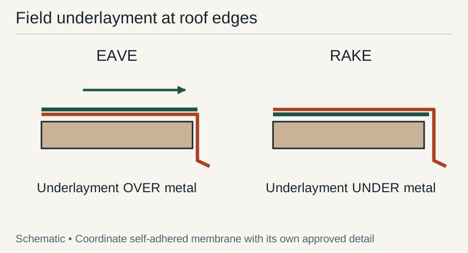
The model section also addresses metal overlap, projection, deck extension and fastening. Have the installer identify those dimensions and the required fastener from the adopted provision and product instructions. A wind-exposed roof may need additional assembly requirements. Keeping the full detail together avoids combining isolated dimensions from unrelated standards.
Valleys collect water from both roof planes
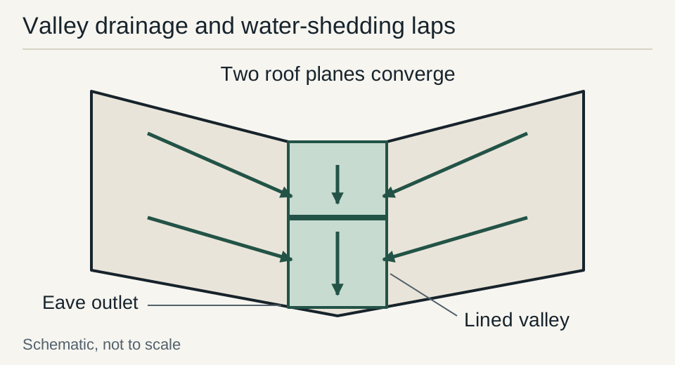
A valley is a concentrated drainage path. Choose the valley type with the roof covering: open metal, closed-cut and other assemblies have different lining and fastening details. The membrane must conform to the deck and discharge into the downstream eave arrangement. Bridging the valley crease leaves unsupported material where water and movement concentrate.
GCP’s cited HT instructions call for valley membrane before eave membrane, with work progressing from the low point upward and laps arranged to shed water. The sheet is centered over the valley and pressed from its center outward. Coordinate that manufacturer sequence with the covering’s valley detail instead of assuming a universal weaving order.
Use the product’s prescribed laps and the roofing manufacturer’s fastener exclusion area. The appropriate shingle cut, metal width and fastener locations depend on the selected assembly. A membrane’s ability to seal around suitable fasteners does not make an open hole, an unsupported fastener or a poorly formed lap acceptable.
Chimneys and roof-to-wall junctions need flashing above the membrane
At a chimney or wall, the underlayment is one part of a layered junction. Coordinate its upturns and terminations with step or base flashing, counterflashing and the wall drainage plane. Water reaching the flashing must have a clear route back onto the roof covering or into the gutter. The upper wall layers should discharge over the relevant flashing rather than behind it.
The assembly differs with the chimney material, roof covering and geometry. Obtain a detail covering corners, changes in slope and the lower termination. At a sidewall eave, a kickout diverter directs concentrated runoff away from the siding. Check those interfaces while they are accessible; an attractive surface sealant bead cannot demonstrate continuity of concealed water-control layers.
Use the building-envelope guide to trace these transitions through the wall and roof. For an addition, include removal and reinstatement of adjoining finishes in the remodeling scope, so the crew has access to connect the existing drainage plane to the new work.
Choose high-temperature underlayment by the named product
The GCP HT sheet describes high-temperature resistance up to 260°F (127°C) and a membrane thickness of 40 mil (1.02 mm). Those product properties are a useful selection reference for compatible roof assemblies. They should be compared with the panel supplier’s required underlayment, substrate and exposure conditions.
Surface appearance alone does not establish temperature capability. A granular membrane and a smooth film membrane may have different intended uses and compatibility restrictions. Check the actual product data sheet, rather than using “high temperature” as an interchangeable category across brands or assuming every metal roof needs the same temperature rating.
The cited GCP sheet specifically directs high-altitude copper, Cor-Ten and zinc applications to its butyl-based GRACE ULTRA product, and calls for appropriate ventilation beneath corrosion-sensitive coverings. It also identifies compatibility restrictions for materials including EPDM and TPO. Resolve transitions between different roof systems with the suppliers before installation.
Full-deck membrane coverage affects drying because this HT membrane is an air and vapor barrier. Coordinate insulation and ventilation with the roof design. The moisture-control guide explains why a rain-control improvement should be reviewed with the assembly’s drying paths.
Inspection and closeout checklist
Before concealment, compare the installed coverage endpoint with the approved roof section. Check deck condition, adhesion, lap direction, valley conformity, edge transitions, penetrations and repairs. Record product labels and photograph the junctions with enough context to identify their locations.
GCP’s sheet requires repairs to holes, fishmouths and tears; removed fasteners can leave holes that need patching. Follow its repair method and exposure limit, then install the compatible roof covering within the required period. Retain the product instructions and accepted detail with the roof records for future maintenance and replacement work.
Primary Sources & Code References
- 2024 IRC, Chapter 9, R905.1.2 and roof assembly provisions International Code Council · reviewed October 25, 2026
- GRACE ICE & WATER SHIELD HT Data Sheet, GIWS-210-0316 GCP Applied Technologies · reviewed October 25, 2026
- Roof Eaves Sealed with Self-Adhering Membrane in Cold Climates U.S. Department of Energy · reviewed October 25, 2026
Related Engineering Guides
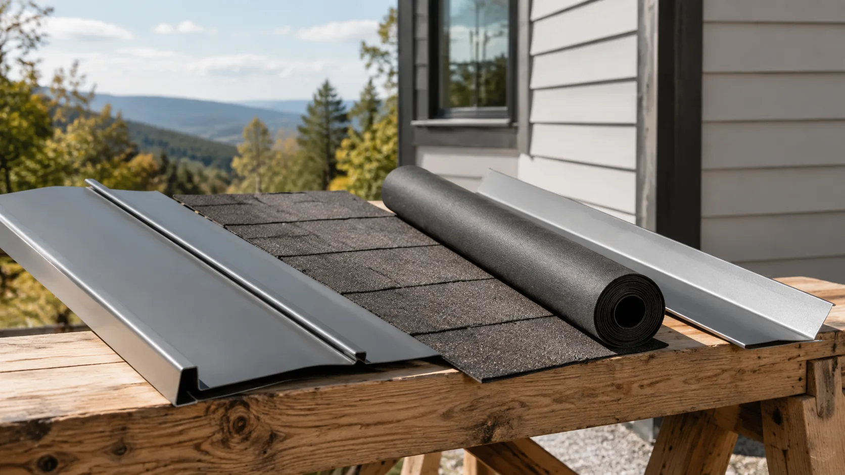
Exterior Siding and Roofing: Drainage, Cladding and Roof Details
Compare fiber-cement, metal and vinyl siding, roof coverings and the flashing connections that keep rain, air and moisture control continuous.
Read technical guide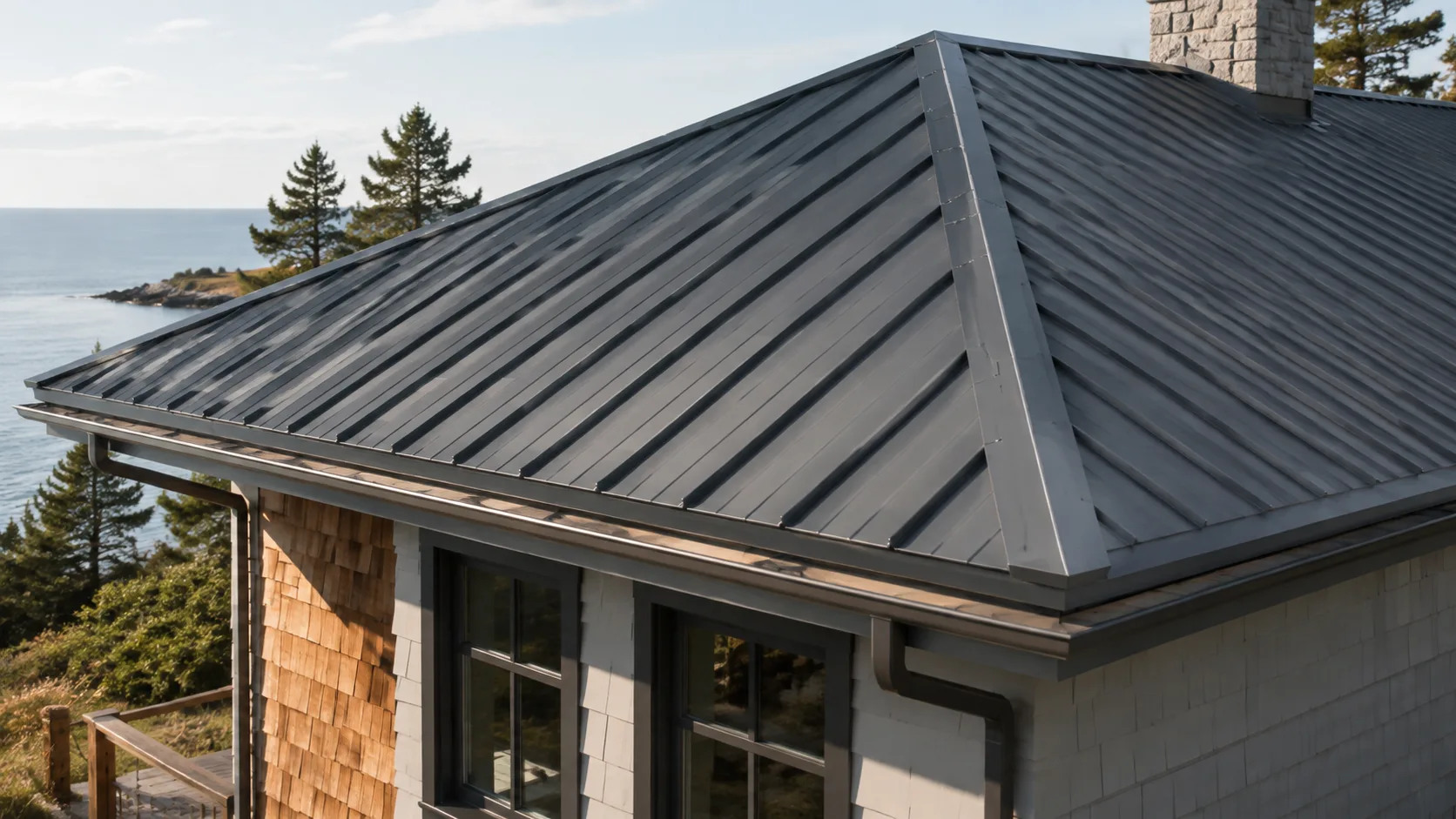
Standing Seam Metal Roof vs. Shingles: Wind, Service Life and Ownership Cost
Compare named metal and shingle specifications, attachment methods, wind-test conditions, warranties and a project-based 50-year ownership-cost framework.
Read technical guide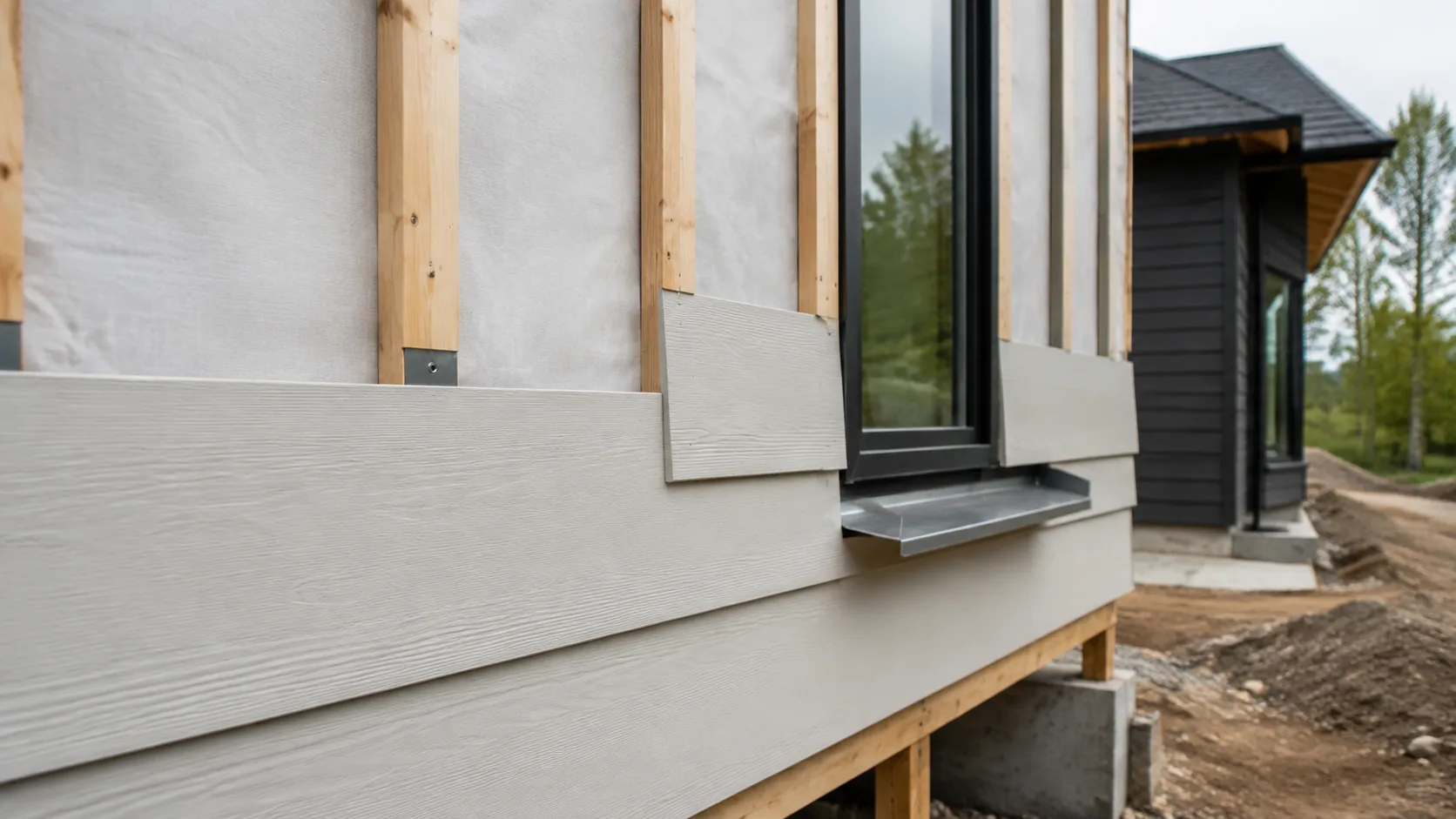
Building Envelope Guide
Understand how roofs, walls, windows, foundations, air barriers, drainage planes, insulation, and HVAC work as one enclosure.
Read technical guide