
Deck Ledger Flashing: Attachment and Water Path
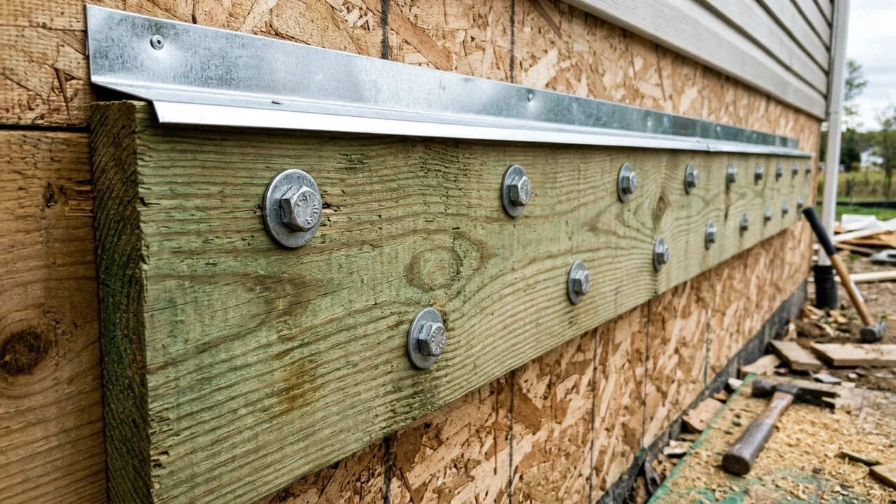
House siding or the exterior finish system must be removed prior to installation of the ledger board, and approved corrosion-resistant flashing is required at any ledger board connection to a wood-framed wall (see Figure 14 continuous flashing detail).
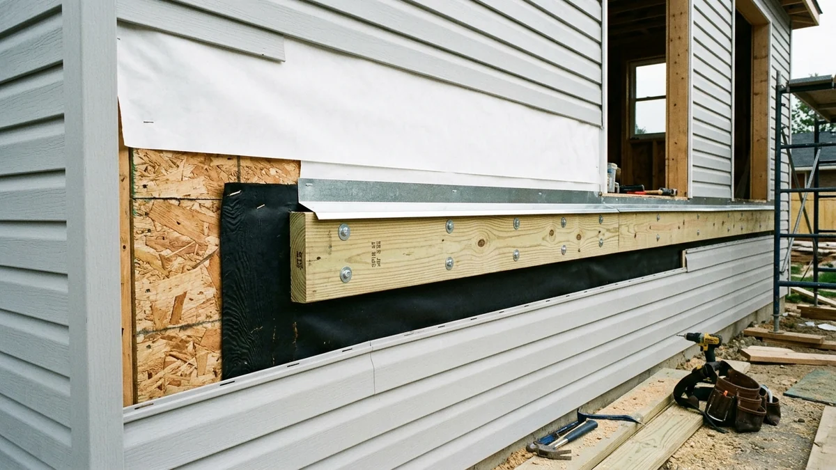
According to the U.S. Department of Energy Building America Solution Center, many deck and porch failures occur at loads well below design loads and can occur without warning. The Building America Solution Center states that the primary causes for failures are deficient connections between the deck ledger and the house rim board and deficient guardrail systems, and that decay and corrosion of fasteners frequently contribute.
Inspecting or specifying a deck ledger connection requires coordinating the exterior drainage order and the structural fastener layout on the same drawing. The exterior siding and roofing guide examines how wall claddings, drainage cavities, and flashings shed water outward across the building enclosure, while the rim joist insulation and air-sealing guide covers the interior air seal and drying path on the inside face of the same perimeter rim board. This guide details the exterior deck ledger flashing sequence, metal and preservative compatibility, band joist verification, and fastener spacing.
Why the Ledger Acts as a Water Dam at Fastener Penetrations
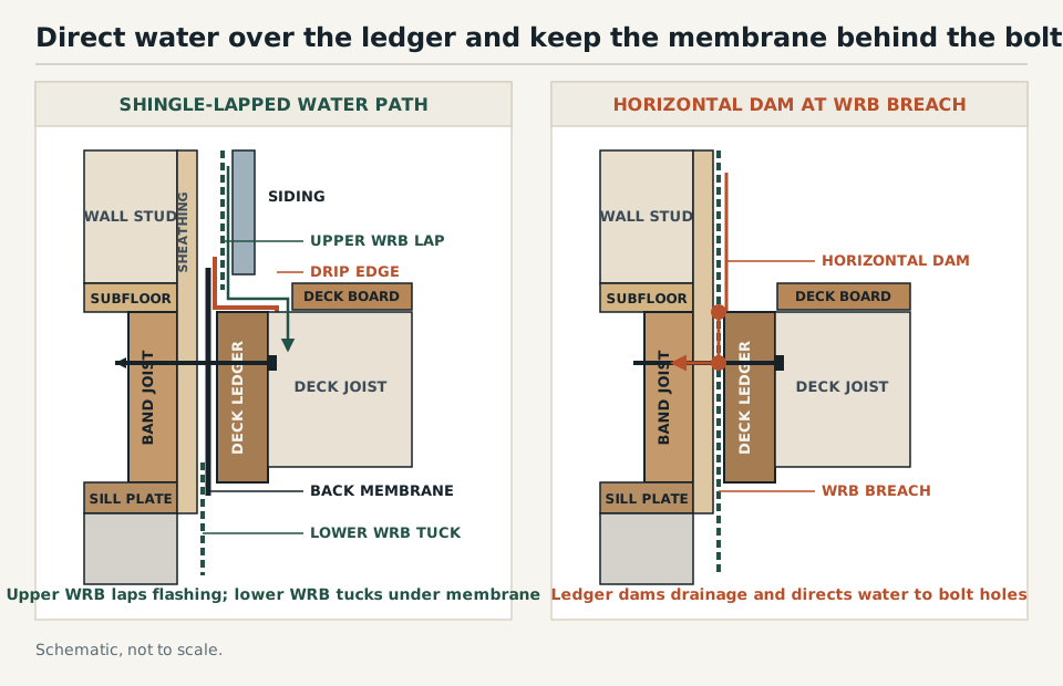
In Info-304, Building Science Corporation explains that when the deck ledger is attached, structural connections breach the water control layer or WRB, and pressed against the water control layer, the ledger acts as a horizontal dam interrupting drainage and potentially directing water to fastener penetrations and into the wall.
In the Home Builder’s Guide to Coastal Construction, FEMA notes that water penetration at deck ledgers can cause wood dry rot and corrosion of connectors leading to deck collapse. The Building America Solution Center adds that deck flashing protects the deck-to-wall connection from water and burning embers. Home Builder’s Guide to Coastal Construction, FEMA P-499, is a report containing 37 fact sheets that provide technical guidance and recommendations concerning the construction of coastal residential buildings.
In the Home Builder’s Guide to Coastal Construction, FEMA states that flashing and other moisture barriers should always be lapped properly, with increased lap lengths for added protection, and that sealant should not be relied on as a substitute for proper lapping.
Sequence the Flashing Layers Behind and Above the Ledger
In the Prescriptive Residential Wood Deck Construction Guide, the American Wood Council states that house siding or the exterior finish system must be removed prior to installation of the ledger board, and that approved corrosion-resistant flashing is required at any ledger board connection to a wood-framed wall (see Figure 14 continuous flashing detail). The Building America Solution Center notes that metal flashing is installed between the deck boards and house wall with the top of the flashing extending up behind the siding and the bottom of the flashing extending out and down over the ledger board.
In Info-304, Building Science Corporation states that where the wall drainage plane is housewrap or building paper applied over structural sheathing, a waterproof membrane should be installed between the ledger board and the sheathing. In Figure 2 of Info-304, for a WRB behind the deck ledger, the drainage plane above the ledger laps over the flashing which is placed over the waterproof membrane, and the drainage plane below the ledger is tucked under the waterproof membrane.
In Figure 1 of Info-304, for flashing over a deck ledger board on continuous insulating sheathing, the ledger flashing directs water out over the deck ledger, membrane flashing integrates the metal flashing into the wall drainage plane, sheathing tape seals the membrane flashing to the drainage plane or sheathing, and deck joist ends are treated to reduce water absorption. In Info-303, Building Science Corporation states that flashings must always direct water out over the cladding or drainage plane without openings that allow water back into the wall, and that flashing tape is applied in order from lower edge to sides to top edge so that it will lap correctly in shingle fashion. Review how these wall transitions connect across the enclosure in the building envelope guide.
| Wall Assembly Condition | Back-Flashing and Drainage Plane Layer | Top Flashing and Outward Drainage Detail |
|---|---|---|
| Housewrap or building paper over structural sheathing | Info-304 | Where the wall drainage plane is housewrap or building paper applied over structural sheathing, a waterproof membrane should be installed between the ledger board and the sheathing. |
| WRB behind the deck ledger | Info-304 Figure 2 | The drainage plane above the ledger laps over the flashing which is placed over the waterproof membrane, and the drainage plane below the ledger is tucked under the waterproof membrane. |
| Continuous insulating sheathing as the drainage plane | In Figure 1, membrane flashing integrates the metal flashing into the wall drainage plane, and sheathing tape seals the membrane flashing. | In Figure 1, ledger flashing directs water out over the deck ledger, and deck joist ends are treated to reduce water absorption. |
| Wood-framed wall connection | House siding or the exterior finish system must be removed prior to installation of the ledger board. | Approved corrosion-resistant flashing is required at any ledger board connection to a wood-framed wall (see Figure 14 continuous flashing detail). |
| Coastal deck flashing recommendations | For coastal deck flashing, use a spacer behind the ledger to provide a gap for drainage, and use stainless steel deck connection hardware. | For coastal deck flashing, leave a gap between the first deck board and flashing to allow for drainage. |
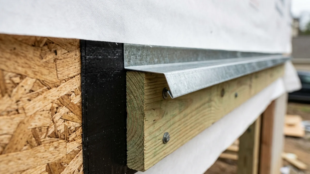
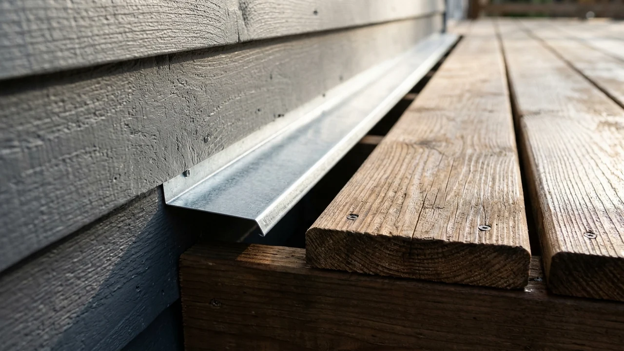
For coastal deck flashing in the Home Builder’s Guide to Coastal Construction, FEMA recommends leaving a gap between the first deck board and flashing to allow for drainage, using a spacer behind the ledger to provide a gap for drainage, and using stainless steel deck connection hardware. In BSI-093, Building Science Corporation states that for wood balconies a drainage slope of one-quarter inch per foot works, the edge needs a drip function so water does not wick inward, and where the edge meets a wall it needs to terminate in a gutter or a kick out. In Info-304, Building Science Corporation states that deck ledger flashing laps over saddle flashing, and that saddle flashing may also be used for railing connections.
In the Prescriptive Residential Wood Deck Construction Guide, the American Wood Council states that the door threshold at a deck shall be carefully flashed and caulked to prevent water intrusion due to splash from the deck or melting snow and ice. According to IRC R311.3.1 as cited in the Prescriptive Residential Wood Deck Construction Guide, the distance from the top of the threshold to the top of deck boards cannot exceed 1-1/2 inches, and if a door does not swing over the landing or deck, the step-down can be up to 7-3/4 inches.
Match Flashing and Fastener Metals to Treated Lumber
The USDA Forest Service Forest Products Laboratory states that if the wood remains dry, the fasteners will not corrode, and explains that after CCA-treated wood was voluntarily withdrawn for residential construction in 2004, replacements such as alkaline copper quaternary (ACQ) and copper azole (CuAz) used copper as a biocide in a higher concentration than CCA.
In item 11 of the Prescriptive Residential Wood Deck Construction Guide, citing IRC R703.8, the American Wood Council states that flashing shall be corrosion-resistant metal of minimum nominal 0.019-inch thickness or approved non-metallic material. The Prescriptive Residential Wood Deck Construction Guide also states that aluminum should not be used in direct contact with lumber treated with preservatives that contain copper such as ACQ, Copper Azole, or ACZA. The City of Lino Lakes Building Inspections Division handout states that Sodium Borate may not be used for outdoor applications, that aluminum should not be in contact with the new treated woods, that flashing between house and deck should be galvanized, stainless steel, or vinyl, and that metal products should not be mixed. In the Home Builder’s Guide to Coastal Construction, FEMA states that fasteners used with flashing should be compatible with or of the same type of metal as the flashing material.
In the Prescriptive Residential Wood Deck Construction Guide, the American Wood Council states that all screws, bolts, washers, nuts, and nails for use with preservative-treated wood shall be hot-dipped zinc-coated galvanized steel, stainless steel, silicon bronze, or copper. Compare these fastener and flashing specifications with the building materials guide during product selection.
| Component or Exposure Condition | Scope in the Cited Guide | Required Material or Coating Standard |
|---|---|---|
| Metal deck flashing thickness | Prescriptive Residential Wood Deck Construction Guide item 11 | Flashing shall be corrosion-resistant metal of minimum nominal 0.019-inch thickness or approved non-metallic material. |
| Copper-treated wood flashing contact | Prescriptive Residential Wood Deck Construction Guide | Aluminum should not be used in direct contact with lumber treated with preservatives that contain copper such as ACQ, Copper Azole, or ACZA. |
| Fasteners in preservative-treated wood | Prescriptive Residential Wood Deck Construction Guide | All screws, bolts, washers, nuts, and nails for use with preservative-treated wood shall be hot-dipped zinc-coated galvanized steel, stainless steel, silicon bronze, or copper. |
| Hot-dipped galvanized fasteners | Prescriptive Residential Wood Deck Construction Guide | Hot-dipped galvanized fasteners shall meet the requirements of ASTM A 153, Class D for fasteners 3/8-inch diameter and smaller or Class C for fasteners with diameters over 3/8 inch. |
| Mechanically galvanized fasteners | Prescriptive Residential Wood Deck Construction Guide | Fasteners other than nails and timber rivets shall be permitted to be of mechanically deposited zinc-coated steel with coating weights in accordance with ASTM B 695, Class 55, minimum. |
| Galvanized hardware and connectors | Prescriptive Residential Wood Deck Construction Guide | Hardware to be hot-dipped prior to fabrication shall meet ASTM A 653, G-185 coating, and hardware to be hot-dipped galvanized after fabrication shall meet ASTM A 123. |
| Outdoor metal connectors | Building America Solution Center | Metal connectors should be hot-dip galvanized in accordance with the ASTM A653, G185 designation. |
| Outdoor fasteners | Building America Solution Center | Fasteners should be hot-dip galvanized in accordance with ASTM A153, Class D. |
| Structural bolts, nuts, and washers | International Residential Code Table R507.2.3 | Bolts and lag screws, including nuts and washers, shall comply with ASTM A307 for bolts, ASTM A563 for nuts, and ASTM F844 for washers, and holes for bolts shall be drilled a minimum 1/32 inch and a maximum 1/16 inch larger than the bolt. |
| Saltwater shoreline exposure | Prescriptive Residential Wood Deck Construction Guide | Fasteners and connectors exposed to salt water or located within 300 feet of a salt water shoreline shall be stainless steel grade 304 or 316, and fasteners and connectors shall be of the same corrosion-resistant material. |
| Coastal and waterfront environments | Building America Solution Center | Use type 316 stainless steel connectors and fasteners for coastal/waterfront and exterior environments where a higher level of corrosion resistance is desired. |
Verify the House Band Joist, Sheathing Gap, and Prohibited Substrates
In the International Residential Code reorganization summarized by the American Wood Council, deck ledger connection provisions were renumbered from R507.1 and R507.2 to R507.9, with R507.9.1.1 Ledger details, R507.9.1.2 Band joist details, R507.9.1.3 Ledger to band joist fastener details, and R507.9.2 Deck lateral load connection. Follow how floor framing and rim boards transfer gravity and lateral loads into the foundation in the structural framing and foundations guide.
In the Prescriptive Residential Wood Deck Construction Guide, the American Wood Council states that the ledger board shall be equal to or greater than the deck joist depth but less than or equal to the house band or rim joist depth, and that the ledger shall be a minimum nominal 2x8. Under IRC Section R507.9.1.2, band joists supporting a ledger under Section R507.2 shall be a minimum 2-inch-nominal solid-sawn spruce-pine-fir or better lumber or a minimum 1-inch by 9-1/2-inch dimensional Douglas fir or better laminated veneer lumber.
The Prescriptive Residential Wood Deck Construction Guide notes that many new homes constructed with wood I-joists include 1-inch or thicker laminated veneer lumber (LVL) band joists that can support a deck attachment, whereas some older homes with band boards thinner than 1 inch require a non-ledger deck or a full plan submission. For engineered wood product rim joists in the Prescriptive Residential Wood Deck Construction Guide, tabulated values are based on 300 lbs for a 1-inch LVL rim joist and 350 lbs for a 1-1/8-inch LVL rim joist. By contrast, the Prescriptive Residential Wood Deck Construction Guide states that metal plate connected wood trusses often have a 2x4 lumber ribbon board at the ends of the trusses that is not intended by itself to support a deck ledger, requiring a standard detail provided by the truss designer, a non-ledger deck, or a full plan submission.
Under IRC Section R507.9.1.1, deck ledgers installed in accordance with Section R507.2 shall not support concentrated loads from beams or girders and shall not be supported on stone or masonry veneer. The Prescriptive Residential Wood Deck Construction Guide states that attachments to exterior veneers (brick, masonry, stone), hollow masonry, and to cantilevered floor overhangs or bay windows are prohibited, requiring a non-ledger deck in such cases, and that lead anchors are prohibited.
Sheathing thickness and drainage spacers must also stay within the dimensional limits of the Prescriptive Residential Wood Deck Construction Guide:
- The maximum gap between the face of the ledger board and the face of the wall sheathing shall be 1/2 inch.
- Stacked washers are permitted in combination with wood structural panel sheathing, but are not permitted in combination with gypsum board or foam sheathing, and the maximum distance between the face of the ledger board and the face of the band joist shall be 1 inch.
Check Fastener Spacing, Staggered Rows, and Pilot Holes
In its Code Official’s Guide to Deck Ledger Connection, the American Wood Council states that residential codes specify an occupant deck live load of 40 pounds-per-square foot (psf), that the Code Official’s Guide spacing table is based on Deck Live Load = 40 psf and Deck Dead Load = 10 psf, and that the IRC has prohibited the use of nails subject to withdrawal as the sole method of attachment. The Prescriptive Residential Wood Deck Construction Guide states that the maximum allowable lateral design value of 725 lbs for 1/2-inch bolts and 385 lbs for 1/2-inch lag screws is based on testing at Virginia Tech and Washington State University.
In the AWC Code Official’s Guide to Deck Ledger Connection, across the joist span bands from 6’-0” and less through 16’-1” to 18’-0”, the on-center fastener spacings are:
| Fastener and Rim Board Combination | 6’-0” and less | 6’-1” to 8’-0” | 8’-1” to 10’-0” | 10’-1” to 12’-0” | 12’-1” to 14’-0” | 14’-1” to 16’-0” | 16’-1” to 18’-0” |
|---|---|---|---|---|---|---|---|
| 1/2-inch diameter lag screw into 1-1/2-inch lumber | 30 in. | 23 in. | 18 in. | 15 in. | 13 in. | 11 in. | 10 in. |
| 1/2-inch diameter bolt with 15/32-inch maximum sheathing into 1-1/2-inch lumber (no stacked washers) | 36 in. | 36 in. | 34 in. | 29 in. | 24 in. | 21 in. | 19 in. |
| 1/2-inch diameter bolt with 15/32-inch maximum sheathing and 1/2-inch stacked washers into 1-1/2-inch lumber | 36 in. | 36 in. | 29 in. | 24 in. | 21 in. | 18 in. | 16 in. |
| 1/2-inch diameter bolt with 15/32-inch maximum sheathing into 1-inch EWP | 24 in. | 18 in. | 14 in. | 12 in. | 10 in. | 9 in. | 8 in. |
| 1/2-inch diameter bolt with 15/32-inch maximum sheathing into 1-1/8-inch EWP | 28 in. | 21 in. | 16 in. | 14 in. | 12 in. | 10 in. | 9 in. |
The AWC Code Official’s Guide states that 1/2-inch lag screws have a hex-head that is 3/4-inch wide, and that lag screws or bolts should be staggered in two rows located at least 2 inches from the top and side edges of the ledger and at least 3/4 inch from the bottom edge. In the Prescriptive Residential Wood Deck Construction Guide, for a 1-1/2-inch ledger and rim board with 1/2-inch fasteners, per 11.5.1.3 of the NDS the maximum spacing between fasteners is 5 inches.
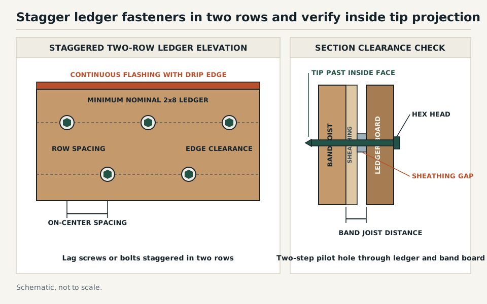
The Prescriptive Residential Wood Deck Construction Guide sets the following pilot-hole, penetration, and lateral-restraint requirements:
- Through-bolts shall have a diameter of 1/2 inch, pilot holes for through-bolts shall be 17/32 inch to 9/16 inch in diameter, and through-bolts require washers at the bolt head and nut.
- For 1/2-inch lag screws, drill a 1/2-inch diameter hole in the ledger board and drill a 5/16-inch diameter hole into the band board; do not drill a 1/2-inch diameter hole into the band joist, and do not drive lag screws with a hammer.
- The tip of the lag screw shall fully extend beyond the inside face of the band or rim joist.
- Hold-down tension devices shall be provided in not less than two locations within two feet of the edge of the deck and shall have an allowable stress design capacity of not less than 1,500 lb.
Record Bolt Spacing and Wall Sheathing Before Repair or Replacement
When evaluating an existing deck ledger or preparing a repair scope, record these four items from the field inspection:
- Exterior siding removal and continuous flashing: Confirm that house siding or the exterior finish system has been removed prior to installation of the ledger board and that approved corrosion-resistant flashing is installed at the ledger board connection to the wood-framed wall (per the applicable Figure 14 continuous-flashing detail).
- Wall sheathing and waterproof membrane order: Where the wall drainage plane is housewrap or building paper applied over structural sheathing, confirm that a waterproof membrane is installed between the ledger board and the sheathing.
- Band joist material and thickness: Verify whether the band joist supporting the ledger under Section R507.2 is a minimum 2-inch-nominal solid-sawn spruce-pine-fir or better lumber or a minimum 1-inch by 9-1/2-inch dimensional Douglas fir or better laminated veneer lumber.
- Ledger bolt or lag-screw spacing and stagger: Record the deck joist span and verify that lag screws or bolts are staggered in two rows located at least 2 inches from the top and side edges of the ledger and at least 3/4 inch from the bottom edge.
Send the ledger bolt or lag-screw on-center spacing (with the deck joist span) and the existing wall cladding and sheathing type through the project reference form. Pair those field notes with the exterior siding and roofing guide so the flashing outlet and the structural attachment are coordinated together.
Can exterior sealant replace shingle-lapped flashing at the deck ledger? Flashing and other moisture barriers should always be lapped properly, with increased lap lengths for added protection, and sealant should not be relied on as a substitute for proper lapping.
Why is aluminum flashing excluded from direct contact with copper-treated deck ledgers? Aluminum should not be used in direct contact with lumber treated with preservatives that contain copper such as ACQ, Copper Azole, or ACZA.
When are stacked washers allowed behind a deck ledger board? Stacked washers are permitted in combination with wood structural panel sheathing, but are not permitted in combination with gypsum board or foam sheathing, and the maximum distance between the face of the ledger board and the face of the band joist shall be 1 inch.
What pilot holes are required for 1/2-inch lag screws at a deck ledger? Drill a 1/2-inch diameter hole in the ledger board and drill a 5/16-inch diameter hole into the band board; do not drill a 1/2-inch diameter hole into the band joist and do not drive lag screws with a hammer.
Sources
- U.S. Department of Energy — Building America Solution Center, Porches, Carports, and Deck Attachments
- U.S. Department of Energy — Building America Solution Center, Deck Ledger Flashing and Fastener Details
- U.S. Department of Energy — Building America Solution Center, Metal Flashing Installed Between Deck Boards and House Wall
- Federal Emergency Management Agency — Home Builder’s Guide to Coastal Construction, Roof-to-Wall and Deck-to-Wall Flashing
- Building Science Corporation — Info-304: Integrating Deck Ledger Board with Drainage Plane
- Building Science Corporation — Info-303: Common Flashing Details
- Building Science Corporation — BSI-093: All Decked Out
- American Wood Council — Prescriptive Residential Wood Deck Construction Guide
- American Wood Council — International Residential Code Changes Related to Wood Construction
- American Wood Council — Is Your Deck Safely Connected to Your House? A Code Official’s Guide to Deck Ledger Connection
- USDA Forest Service — Forest Products Laboratory, Corrosion of Fasteners in Wood Treated with Newer Wood Preservatives
- City of Lino Lakes, Minnesota — Building Inspections Division, Informational Handout: ACQ / Treated Wood Fasteners and Flashing
Related Engineering Guides
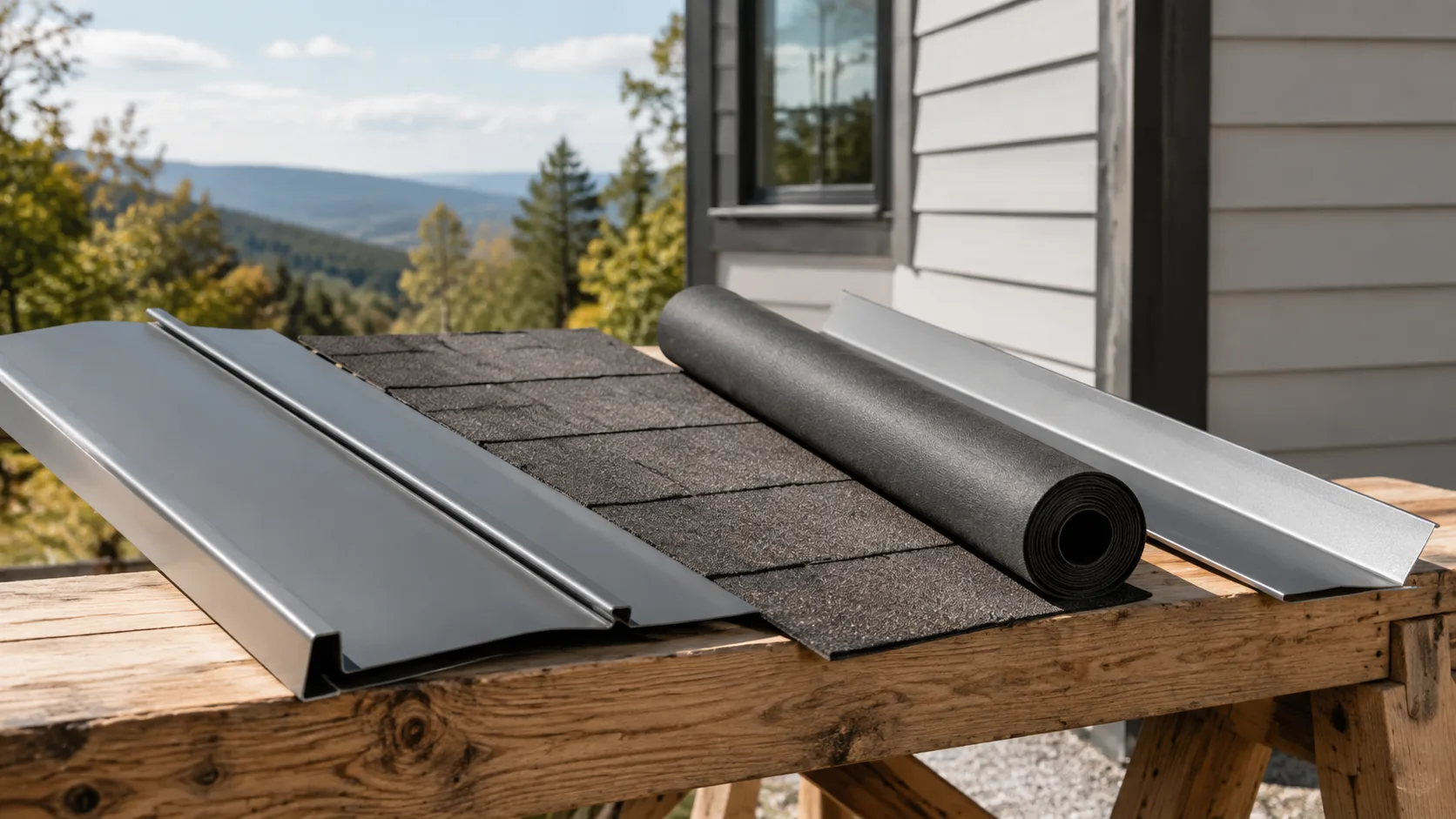
Exterior Siding and Roofing: Drainage, Cladding and Roof Details
Compare fiber-cement, metal and vinyl siding, roof coverings and the flashing connections that keep rain, air and moisture control continuous.
Read technical guide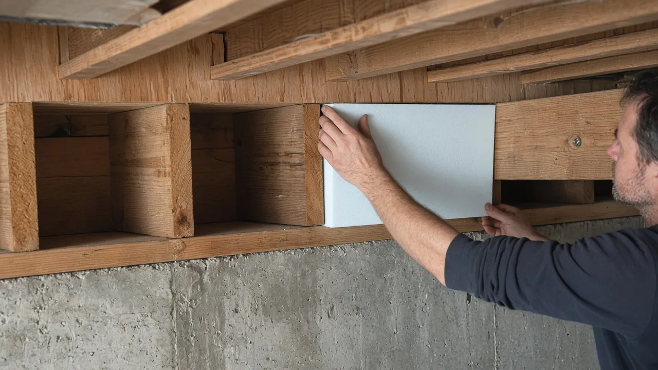
Rim Joist Insulation: Air Seal and Drying Path
Air-seal the rim and band joist to the floor air barrier, then insulate without closing both drying directions of the wood.
Read technical guide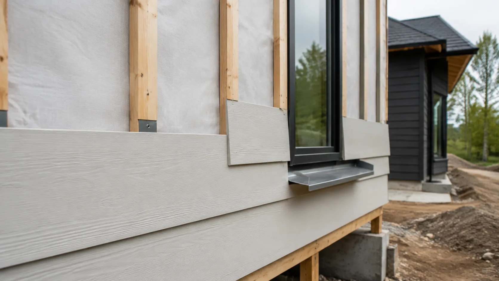
Building Envelope Guide
Understand how roofs, walls, windows, foundations, air barriers, drainage planes, insulation, and HVAC work as one enclosure.
Read technical guide